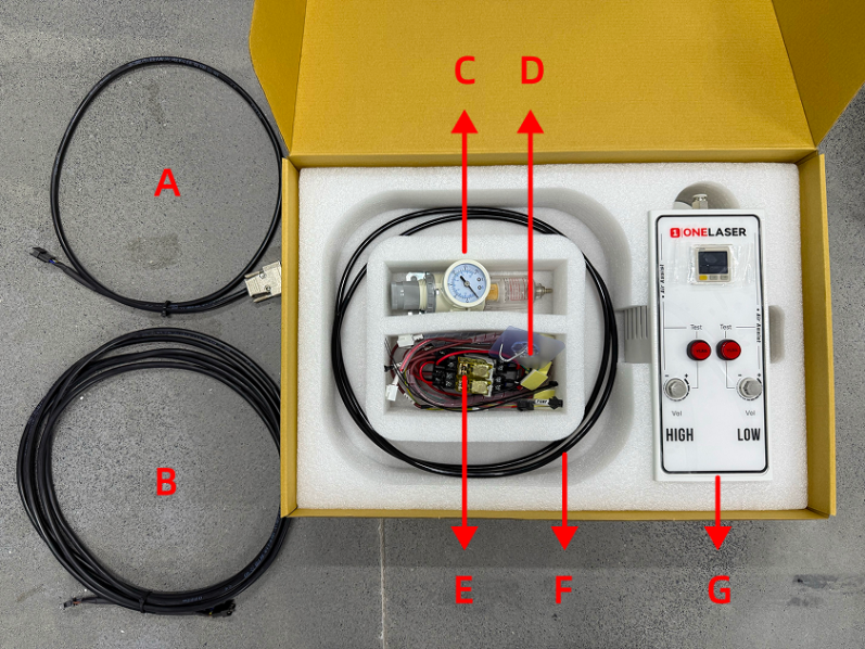
¶ 3.1 Component List in Air Assist Control Box
|
Number |
Name |
|
A |
Control Cable 1 (DB9 Female) |
|
B |
Control Extension Cable 2: Hydra-Series Only (5-Wire Port) |
|
C |
Air Filter Regulator |
|
D |
Cable Ties / Cable Tie Mounts / Adhesive Hook / 6mm to 6mm Adapter |
|
E |
Relays |
|
F |
Air Hose (2.8m) |
|
G |
Air Assist Kit |
¶ 3.2 Pneumatic Installation Instructions
¶ 3.2.1 Gas Source Requirements
A dry, clean gas source must be used, with an operating pressure range between 0-0.7 MPa. Strictly control the water and oil content in the compressed air. Failure to do so may clog the nozzle, contaminate optical lenses, and in severe cases, may cause a fire.
¶ 3.2.2 Connection Steps
Using the Built-in Air Pump:
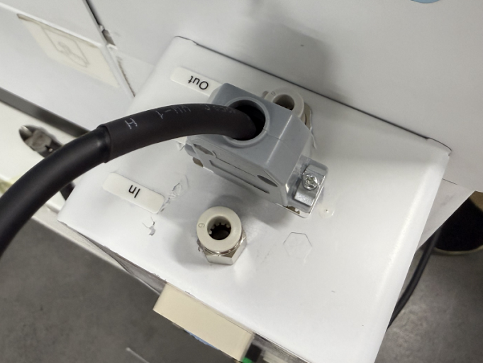
- Connect the Original Air Pump (B): Plug the connector end of the original air pump into the port labeled Output: Air pump located on the lower back (A) of the device. Connect the hose end of the original air pump to the "In" (Inlet) port of the Air Assist Kit (C).
- Connect the Air Assist Kit (C) to the Device: Connect a hose from the Out (Outlet) port of the Air Assist Kit (C) to the port labeled AIR ASSIST 55 PSI MAX / 400 kPa MAX located on the lower back (D) of the device.
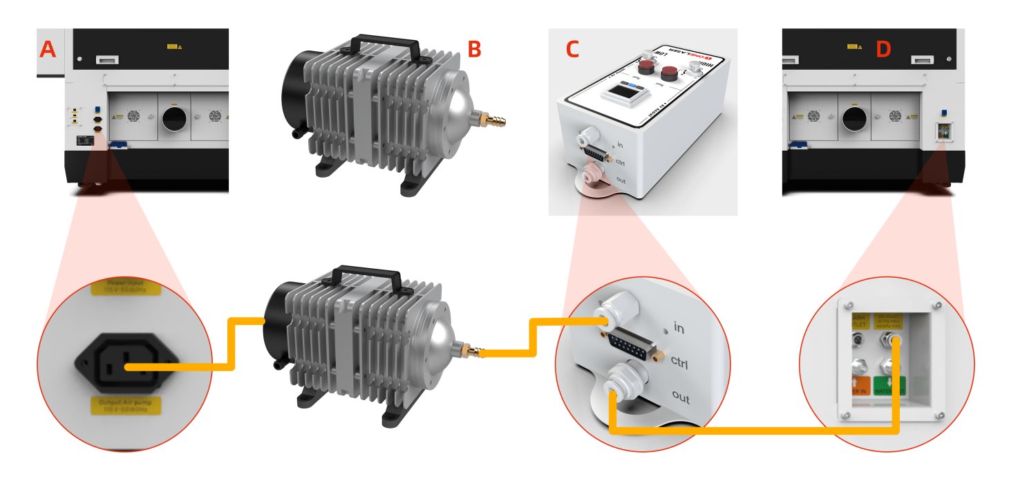
Note: The original air pump delivers lower output pressure, making it suitable for limited scenarios (e.g., thin sheet cutting). For processing a wider range of materials, using an external air compressor system is recommended for significantly improved processing results. Optimized gas source solutions and test data will be continuously updated on the official website. Stay tuned for updates.
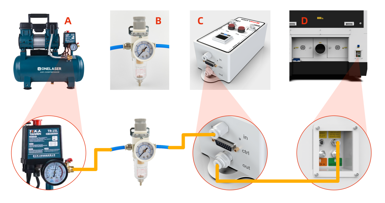
Connecting an External Air Compressor:
Power off the device and disconnect the Power Input located on the lower back of the device before starting any connections.
- Connect Air Compressor (A) to Air Filter Regulator (B): Connect the air hose from the OUTLET port of the Air Compressor (A) to the IN (Inlet) port of the Air Filter Regulator (B).
- Connect Air Filter Regulator (B) to Air Assist Kit (C): Connect the air hose from the OUT (Outlet) port of the Air Filter Regulator (B) to the IN (Inlet) port of the Air Assist Kit (C).
- Connect Air Assist Kit (C) to Device (D): Connect the air hose from the OUT (Outlet) port of the Air Assist Kit (C) to the Gas Source Input Port on the back of the Device (D).
- Verification & Power: Ensure all connections are secure and free from looseness. The air compressor must be powered by an external power source.
Important Note for External Air Compressor Setup:
When using an external air compressor, complete the following steps:
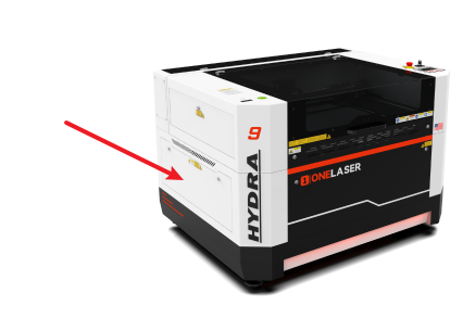
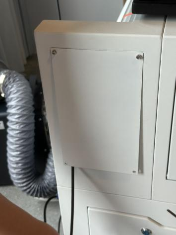
- Access the Regulating Valve: Open the access door/panel located on the lower-left side of the device. Locate the Regulating valve inside this compartment.
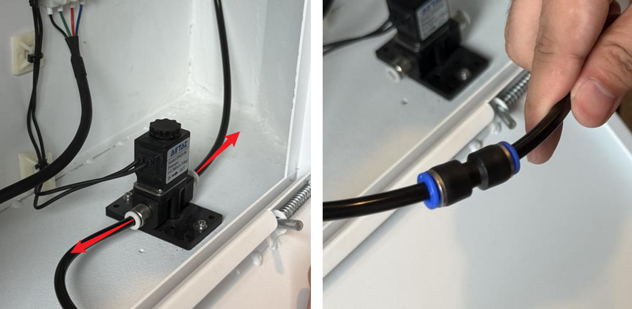
- Modify the Air Hose Connections: Disconnect both the inlet and outlet air hoses from the Regulating valve. Locate the 6mm to 6mm adapter in the accessories kit. Use this adapter to connect the inlet and outlet air hoses directly together (bypassing the Regulating valve).
¶ 3.3 Electrical Circuit Installation Instructions
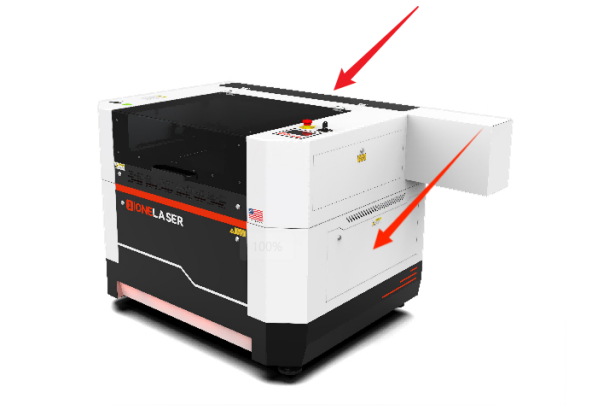
- Access Panels: Power off the device and disconnect the Power Input on the lower back before starting any electrical work. Remove the right-side cover and rear cover (using the Hydra7 as an example).
- Install the Relay: Locate the relay component in the Air Assist Control Box. Install the relay base/mounting bracket. Secure the relay inside the right-side cover enclosure.
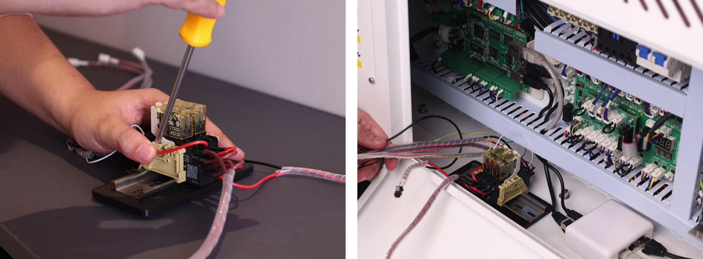
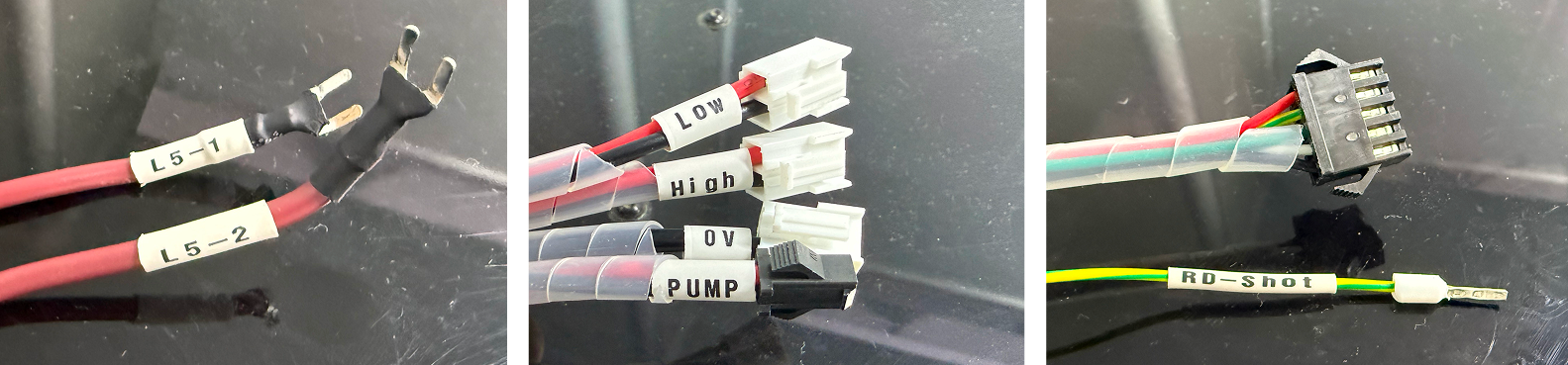
- Locate Components: Find the TL Mainboard. Identify the cable labels on the relay: 0V, LOW, HIGH, PUMP, L5-1, L5-2, RD-Shot.
- Connect Control Wires:
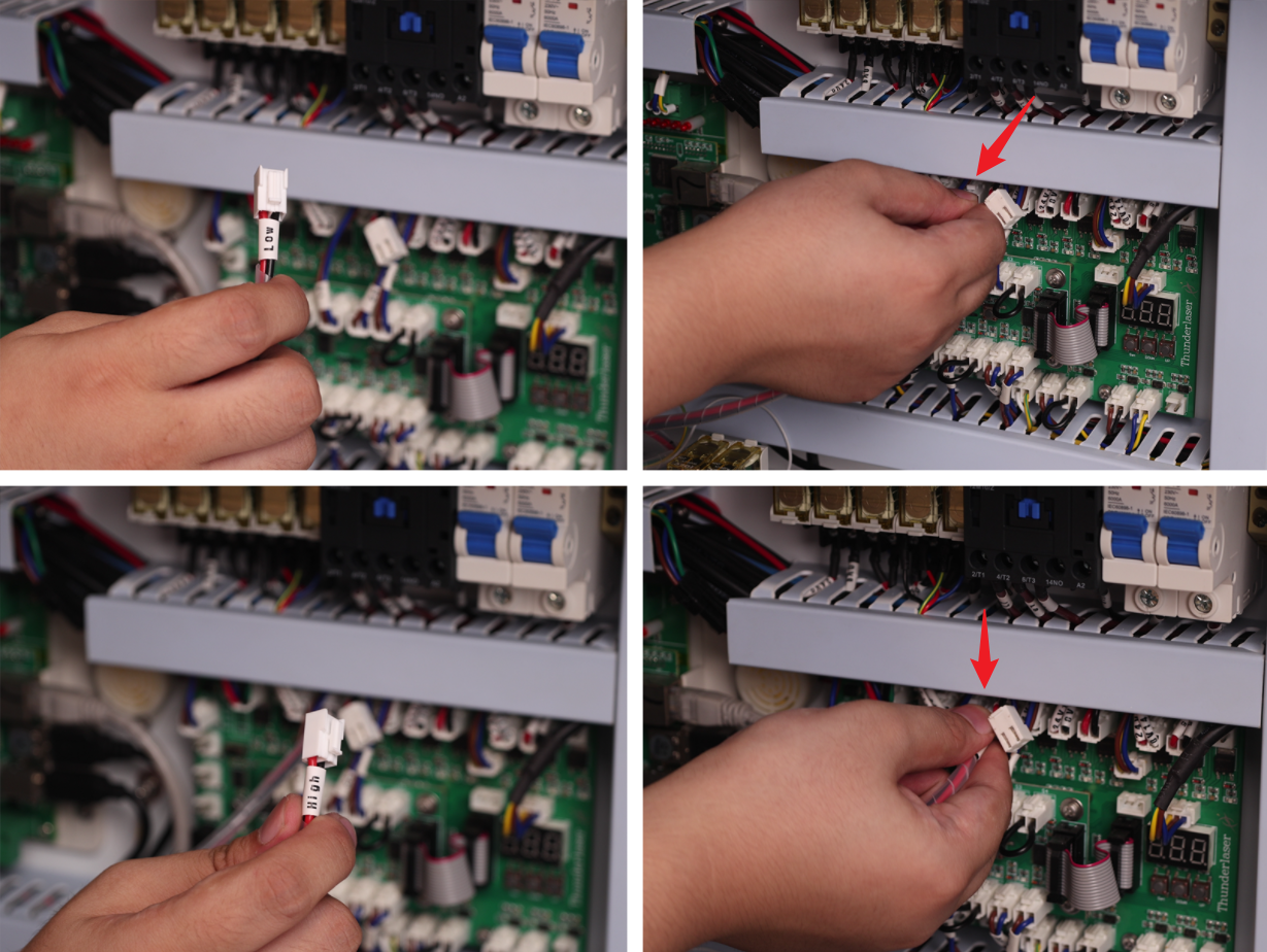
1. LOW → Connect to the OUT 4 24V GND terminal on the top row of the TL Mainboard (the 4th terminal from the left).
2. HIGH → Connect to the OUT 5 24V GND terminal on the top row of the TL Mainboard (the 5th terminal from the left).
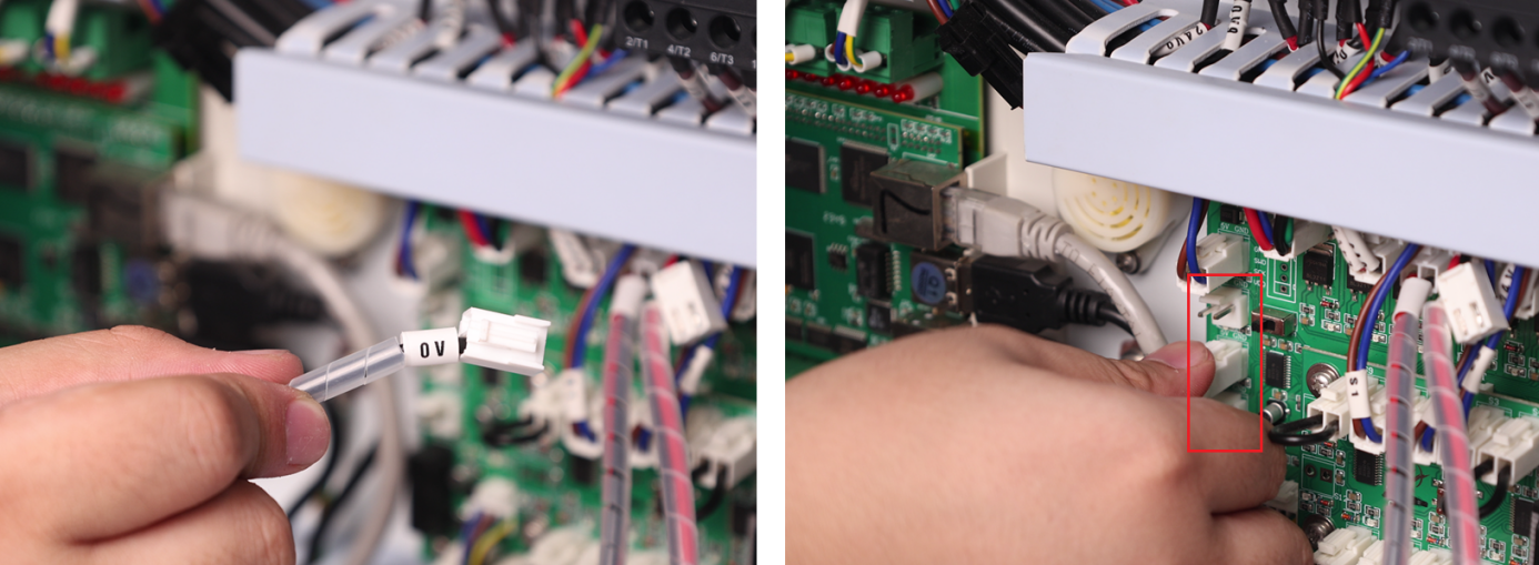
3. 0V → Connect to any 5V GND terminal on the left side of the TL Mainboard (choose 1 of the 3 available terminals).
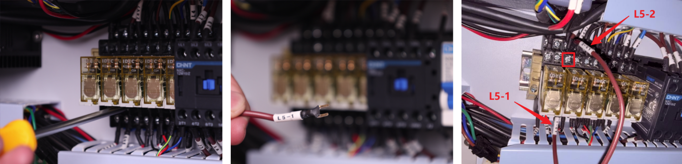
4. L5-1 → Connect to the lower row, 3rd terminal from the left of the device's Relay L5.
5. L5-2 → Connect to the upper row, 3rd terminal from the left of the device's Relay L5.
- Connect the Ctrl Interface:
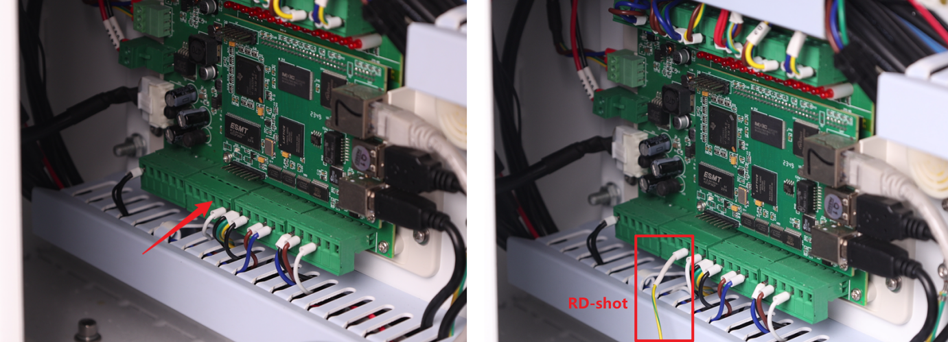
1. Locate the wire labeled RD-shot. Plug it into the 4th small terminal of the 2nd large terminal block located the bottom-left section of the TL Mainboard.
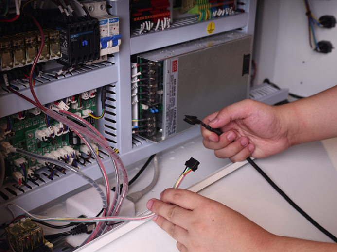
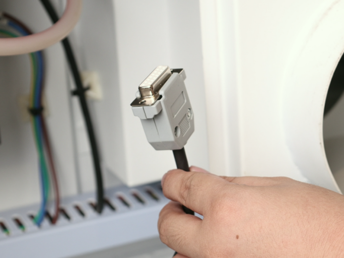
2. Locate Control Cable 1 (DB9 Female) and Control Cable 2 (5-Wire Port) inside the air assist control box. First, mate the two cables together to extend the overall length – we will refer to this combined cable as the "Assembled Cable". Then, connect the 5-Wire Port end of the Assembled Cable to the 5-Wire Port on the relay, as shown in the figure below.
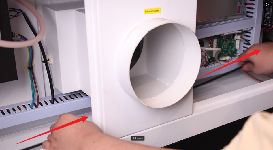
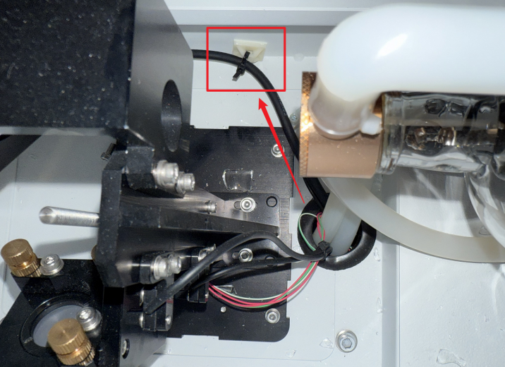
3. Open the access door/panel on the back of the device. Route the connector end of the Assembled Cable through the internal space at the back of the device. Pull it out through the cable pass-through hole in the rear cover.

IMPORTANT SAFETY WARNING:
Due to limited space in the rear cover's cable pass-through holes, improperly routed cables may intrude into the laser optical path. This poses serious risks including: laser beam reflection hazards, burned/cut wires and potential equipment damage.
REQUIRED ACTIONS:
ALL cables MUST be securely fastened using cable ties and cable tie mounts. Cable positions MUST be periodically inspected to prevent the above hazards!
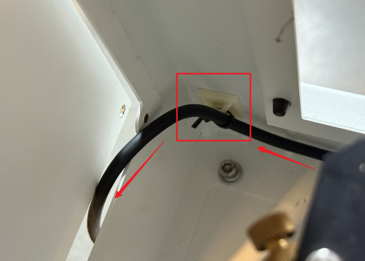
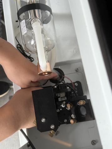
4. Open the small access door/panel on the left side of the device. Pull the connector through this opening towards the Air Assist Kit. Plug the connector into the port labeled "Ctrl" to complete the circuit connection.
- Unused Wire Handling: The PUMP wire does not require connection to any terminal. Securely bundle and stow it away from moving parts or connectors.