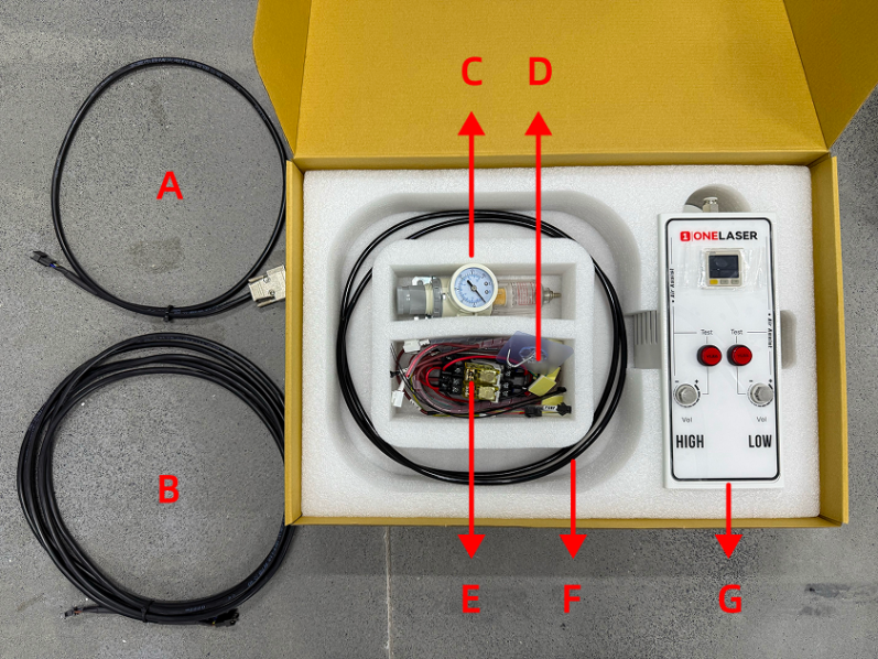
¶ 2.1 Component List in Air Assist Control Box
|
Number |
Name |
|
A |
Control Cable 1 (DB9 Female) |
|
B |
Control Extension Cable 2: Hydra-Series Only (5-Wire Port) |
|
C |
Air Filter Regulator |
|
D |
Cable Ties / Cable Tie Mounts / Adhesive Hook / 6mm to 6mm Adapter |
|
E |
Relays |
|
F |
Air Hose (2.8m) |
|
G |
Air Assist Kit |
¶ 2.2 Pneumatic Installation Instructions
¶ 2.2.1 Gas Source Requirements
A dry, clean gas source must be used, with an operating pressure range between 0-0.7 MPa. Strictly control the water and oil content in the compressed air. Failure to do so may clog the nozzle, contaminate optical lenses, and in severe cases, may cause a fire.
¶ 2.2.2 Connection Steps
Using the Built-in Air Pump:
X-series devices come equipped with a built-in air pump. No installation is required by the user.
Note: The original air pump delivers lower output pressure, making it suitable for limited scenarios (e.g., thin sheet cutting). For processing a wider range of materials, using an external air compressor system is recommended for significantly improved processing results. Optimized gas source solutions and test data will be continuously updated on the official website. Stay tuned for updates.
Connecting an External Air Compressor:
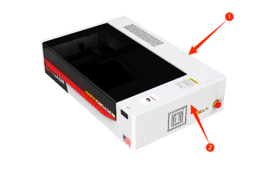
Before connecting, power off the device and disconnect the Power Input located on the lower back of the device.
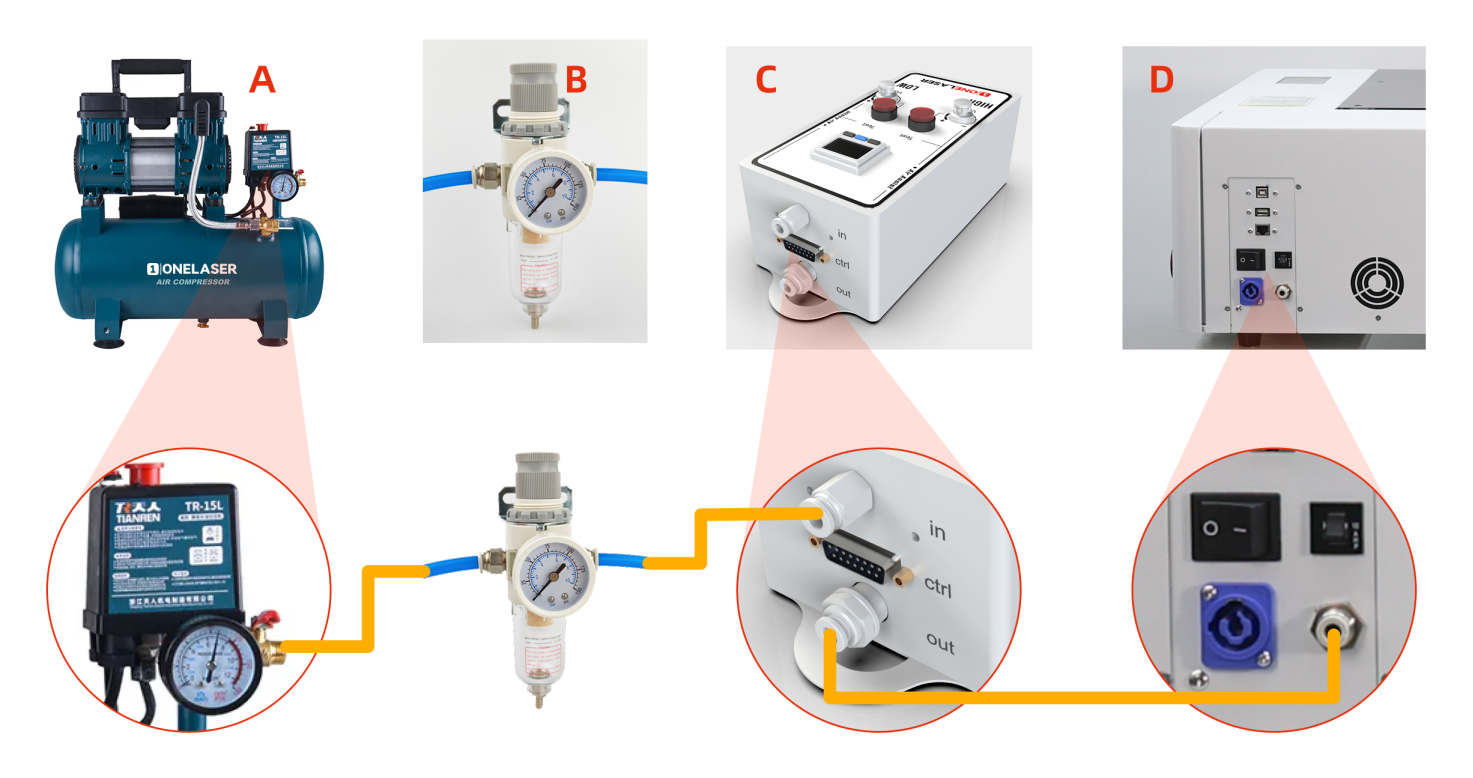
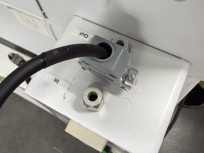
- Connect the Air Compressor (A) to the Air Filter Regulator (B): Connect the air hose from the air compressor's OUTLET to the IN (Inlet) port of the Air filter regulator.
- Connect the Air Filter Regulator (B) to the Air Assist Kit (C): Connect the air hose from the OUT (Outlet) port of the Air filter regulator to the IN (Inlet) port of the air assist kit.
- Connect the Air Assist Kit (C) to the Device (D): Connect the air hose from the OUT (Outlet) port of the air assist kit to the Gas Source Input Port on the back of the device.
Important:
If you are using the XT device, these steps requires transforming the internal connections:
- Remove the rear cover, then remove the right-side cover of the device.
- Disconnect the internal connector found inside the right-side cover area before proceeding (failure to disconnect may cause wiring damage).
- Locate the 6 mm to 6mm adapter. Disconnect the air hose from the compressor side.
- Find the air hose connected internally to the device's external gas inlet port. Insert the free end of this hose into the 6mm to 6mm adapter.
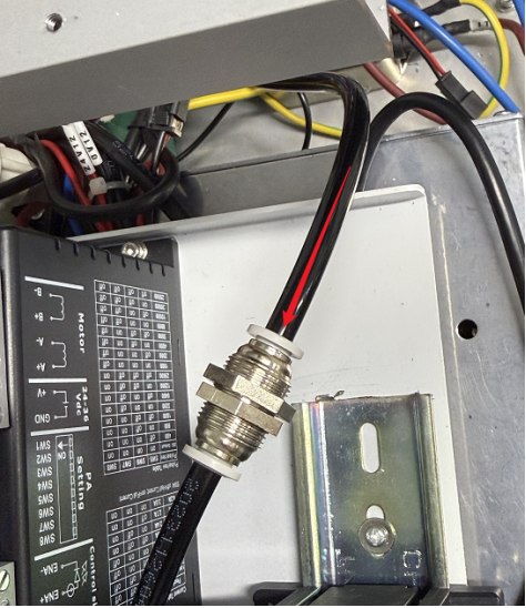
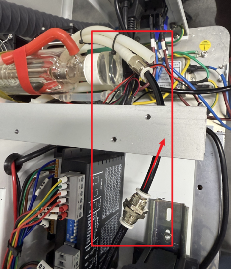
If you are using the XRF device, these steps requires transforming the internal connections:
- Remove the rear cover, then remove the right-side cover of the device.
- Disconnect the internal connector found inside the right-side cover area before proceeding (failure to disconnect may cause wiring damage).
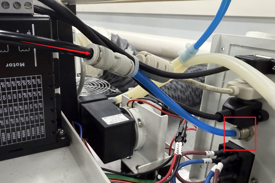
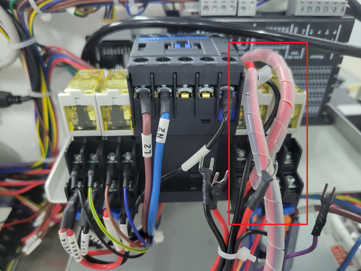
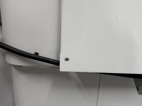
- Locate the connected air hose as shown in the figure below. Disconnect the white air hose while keeping its adapter attached.
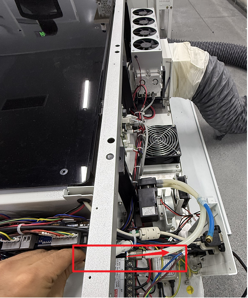
- Find the blue air hose connected internally to the device's external gas inlet port. Insert the black air hose into the 6mm to 6mm adapter.
- Inspection & Confirmation: Ensure all connections are securely fastened without looseness. The air compressor must be powered by an external power source.
¶ 2.3 Electrical Circuit Installation Instructions
- Remove the Covers: Power off the device and disconnect the "Power Input" located on the lower back of the device before starting any electrical connections. Remove the rear cover of the machine. Then, remove the right-side cover.

Important: Disconnect the internal connector located inside the area of the right-side cover before removing the cover. Failure to disconnect it first may cause wiring damage.
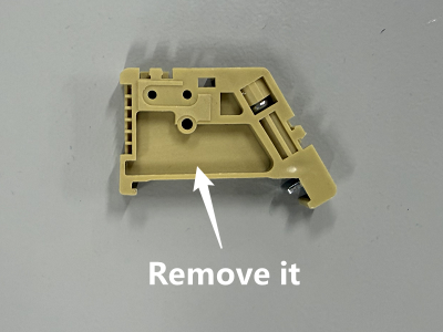
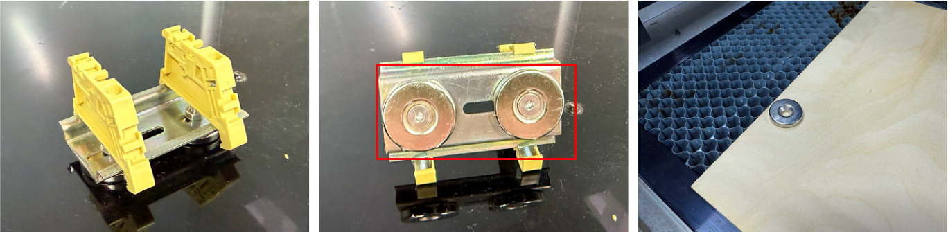
- Install the Relay: Locate the relay component from the Air Assist Control Box. Remove the base and mounting hardware from the air assist kit relay, then detach the existing mounting hardware from the equipment relay. Remount both relays on the DIN rail to complete the installation.
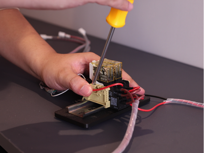
Note: The magnet on the base is removable and can be reused (if needed) for securing materials.
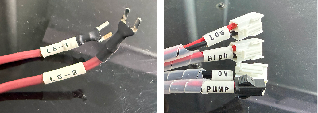
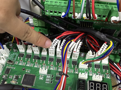
- Locate Components: Find the TL Mainboard (refer to the diagram). Identify the relay cable labels from the Air Assist Control Box: 0V, LOW, HIGH, PUMP, L5-1, L5-2, RD-Shot.
- Connect Control Wires:
- 0V → Connect to any 5V GND terminal on the left side of the TL Mainboard (choose 1 of the 3 terminals marked for 5V GND).
2. LOW → Connect to the OUT 4 24V GND terminal on the TL Mainboard (locate the OUT4 marking on the board).
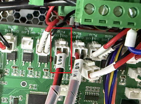
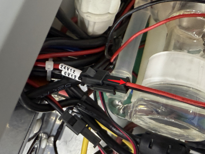
3. HIGH → First, disconnect the plugs currently connected to the OUT 5 24V GND terminal on the TL Mainboard (locate the OUT5 marking). These plugs are typically labeled 0V 12 and 24V 12. Then, connect the "HIGH" control wire to this now vacant OUT 5 24V GND terminal.

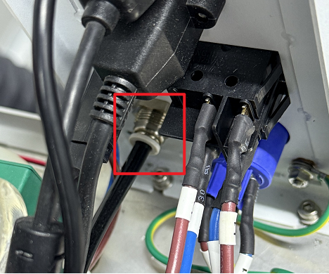
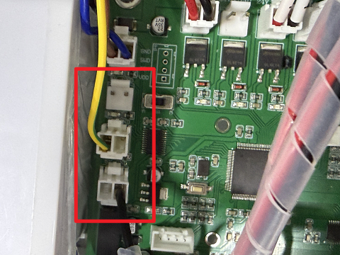
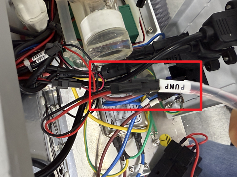
- Reconnect Pump Power:
1. Locate the 24V 12 and 0V 12 terminal pairs on the back of the machine.
2. First, disconnect the original plug(s) from these terminals.
3. Then, connect the PUMP wire to the air pump terminal.
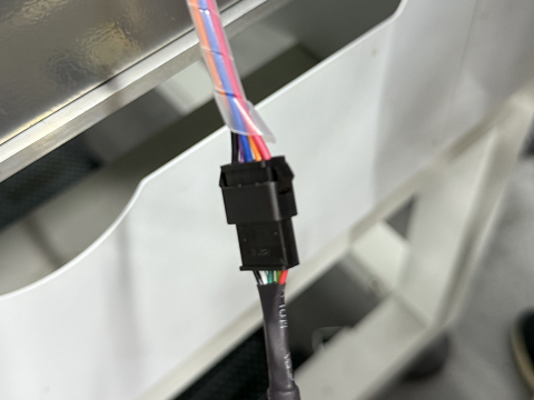
- Connect the Ctrl Interface:
1. Find the Control Cable1(DB9 Female) with the plug shown in the diagram below.
2. Connect the socket end of this cable (opposite the diagrammed plug) to the 5-wire port on the relay.
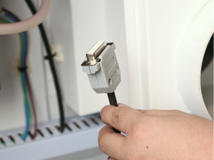
3. Reattach the side cover, ensuring the cable passes through a suitable opening/grommet.
4. Plug the DB9 Female into the port labeled Ctrl on the device to complete the circuit connection.
- Unused Wire Handling: The RD-Shot, L5-1 and L5-2 cables do not require connection. Securely bundle and stow these unused wires away from moving parts or connectors.