¶ How to Use the Camera
This guide explains how to connect, calibrate, and use the camera on the One Laser Hydra series. It covers camera setup in LightBurn, importing calibration files, visual positioning, and contour extraction to help you achieve accurate, camera-assisted processing.
¶ Preparation
- USB cable ×1
- PC ×1
- USB flash drive ×1
- Lightburn software ×1
¶ Connecting the machine and the camera
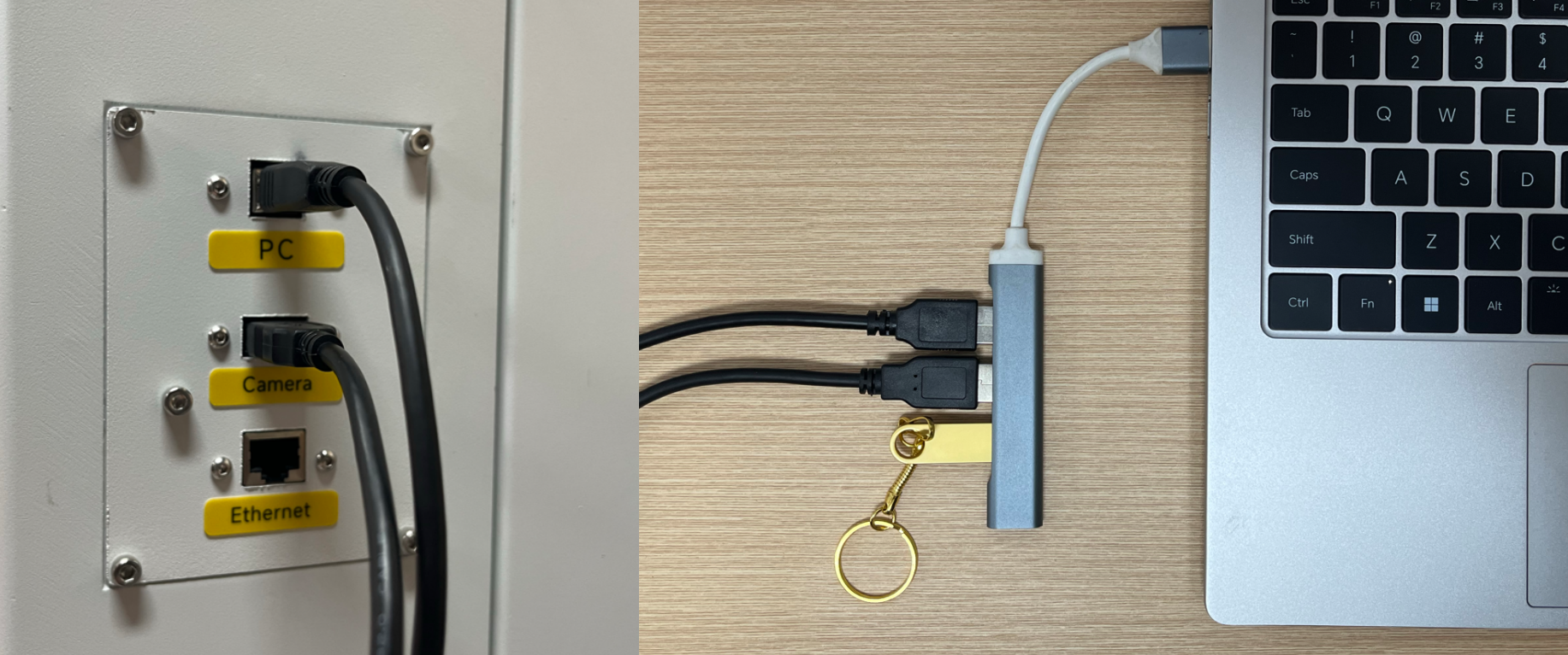
1. Connect the USB cable and PC cable to the computer (USB cable and PC cable are stored in the tool pouch)
2. Connect the Hydra with lightburn, for the connection steps, please click on the link below to watch the tutorial Getting Started With LightBurn: Getting Started With LightBurn: Set up & First Project
Note: The origin for Hydra is Rear left. lt's controller is Ruida
¶ Import Camera Correction File
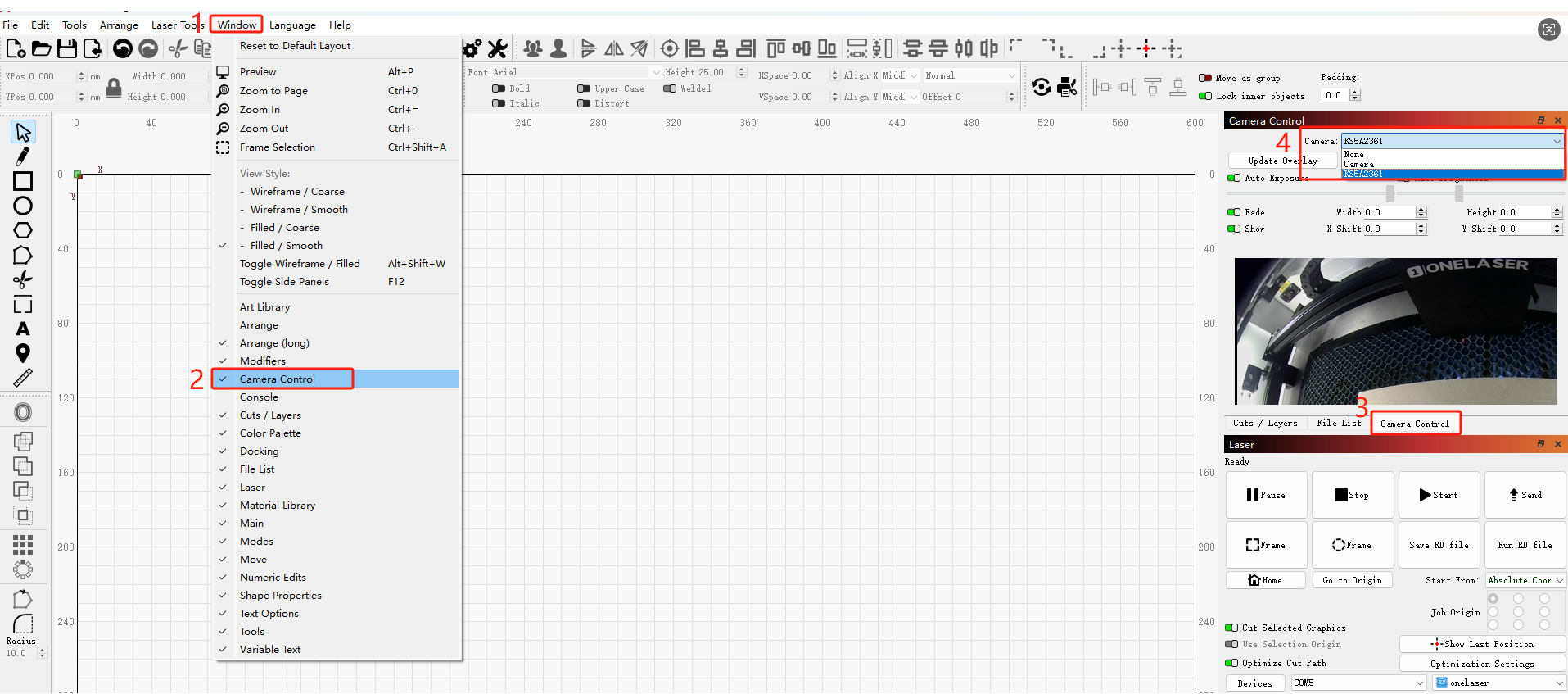
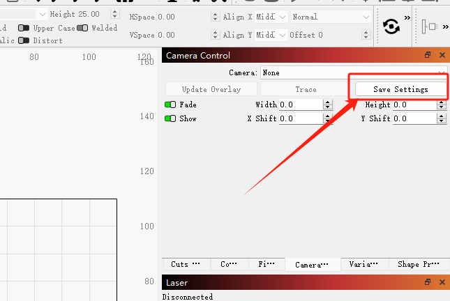
1. In the Lightburn software, click “Window” and “Camera Control” to enable the camera control function, and then select the camera of the machine.
Note: Please go through the camera screen to make sure that the camera has been selected correctly.
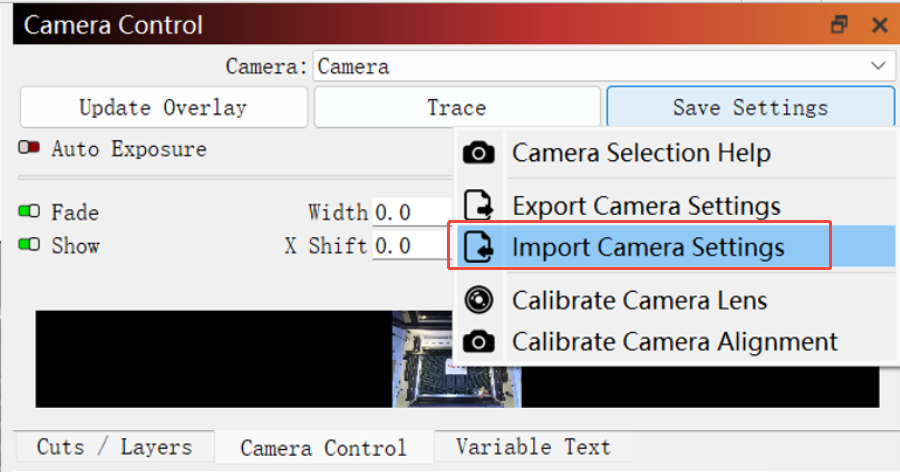
2. Right click on “Save Settings” and select “Import Camera Settings”.
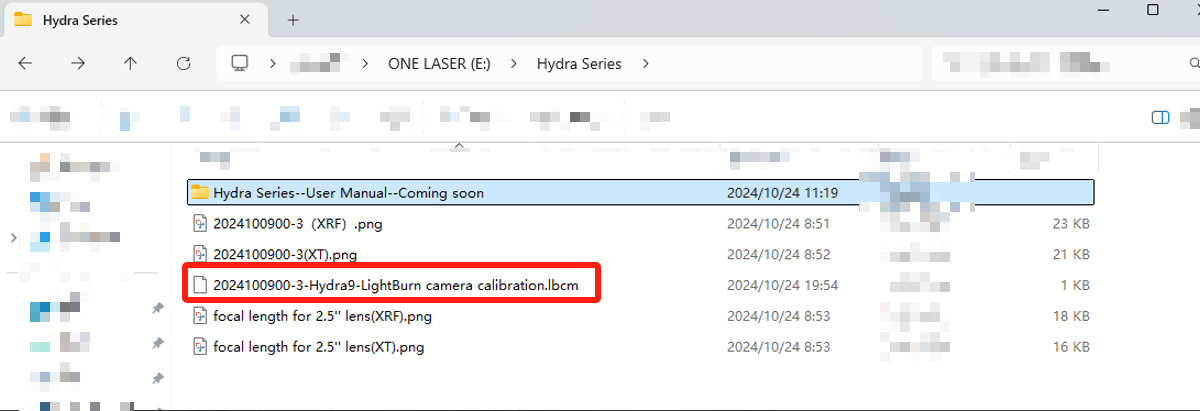
3. Please insert the USB flash drive that came with the machine into your computer, save the camera calibration file in the USB flash drive, and then select and import the calibration file. (.lbcm)
4. After importing the camera calibration file, click “Save Settings” to save the settings.
¶ Using the camera
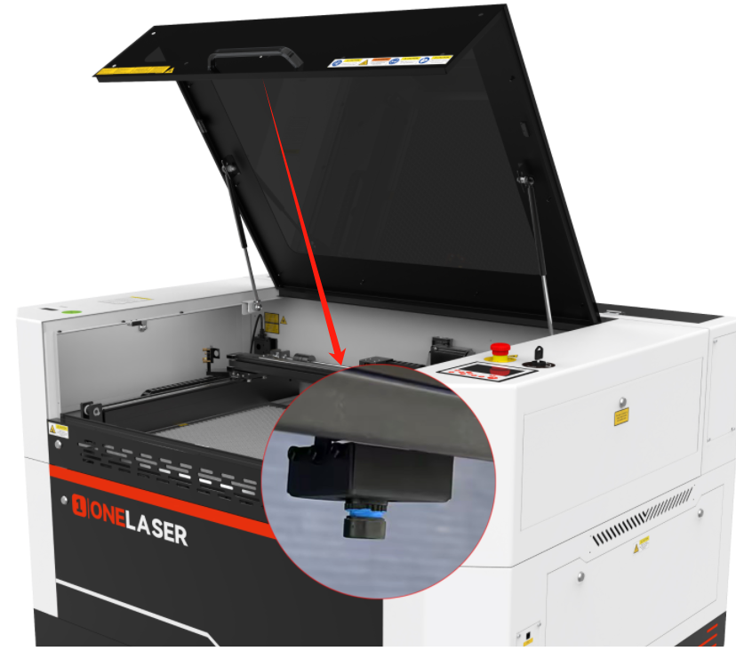
Note: Remove the cover of the camera before use.
¶ Turn off the open cover protection
1. The camera is mounted on the door cover, so you need to keep the door cover open when using the camera.
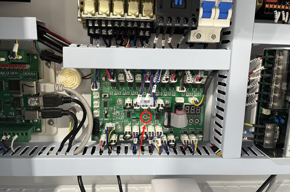
2. You need to open the lower right door cover of the device, locate the door cover tandem control board, and press the button in the figure below.
¶ Visual positioning function
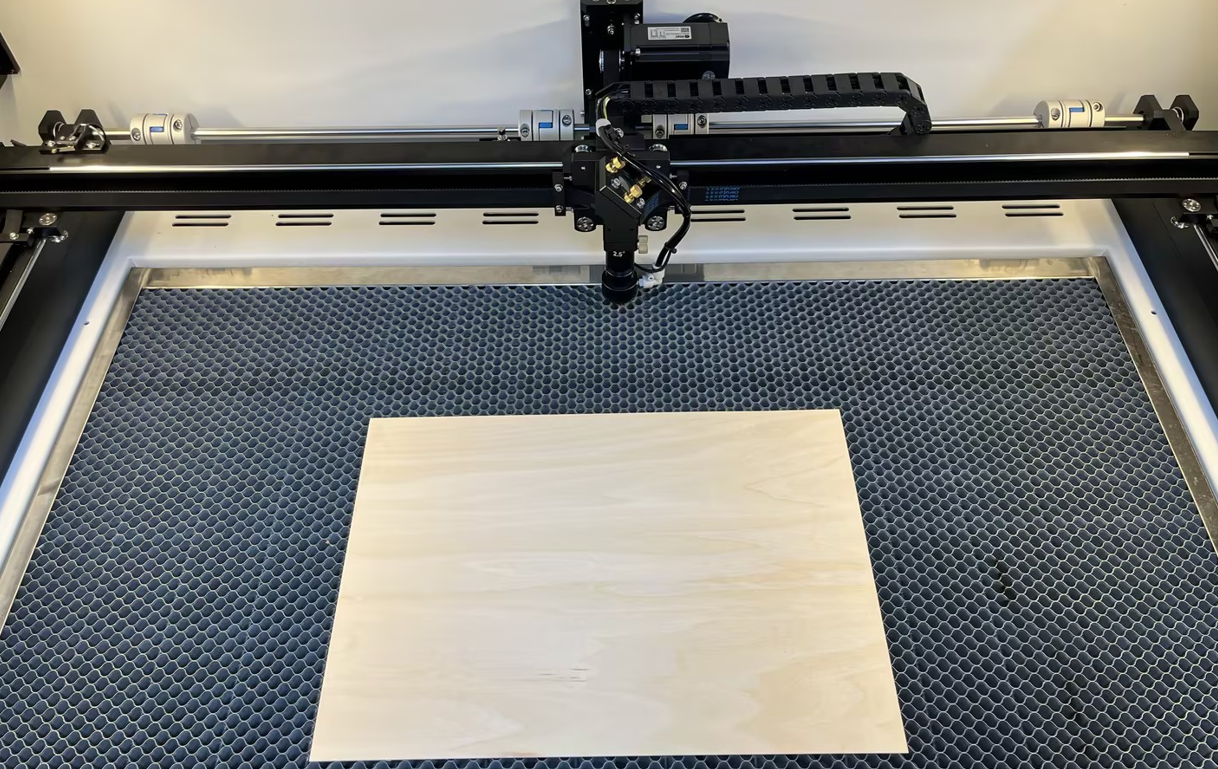
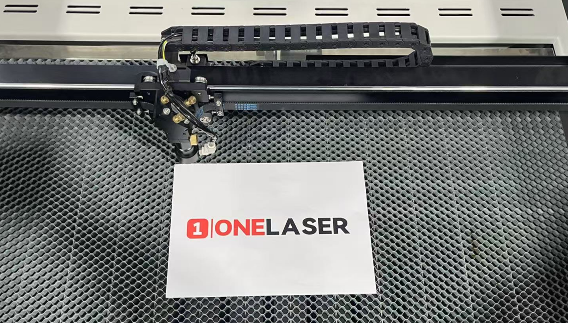
1. Place the material to be processed on the processing platform of the machine and adjust the focus to a suitable position.
Note: During the next operation, please make sure that the door cover is always open.
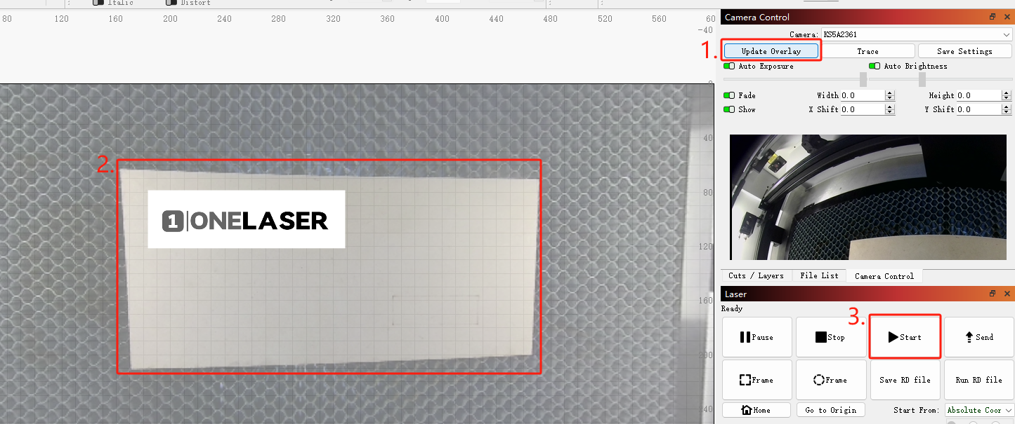
2. Then click the “Update Overlay” button to refresh and display the real-time screen of the machining platform.
Note: If the laser head is blocking the platform screen, please remove it.
3. Import the drawing to be machined and move the drawing to the appropriate machining position.
4. Set the machining parameters and size of the drawing.
5. Directly click “Start” button, the machine will start machining at the set position.
¶ Physical object pattern contour extraction
1. Place the object to be extracted on the processing platform.
2. Click “Trace” to enter the outline extraction interface.
3. You can use the mouse to select the area you want to extract, and adjust the parameters to extract the contour of the object.
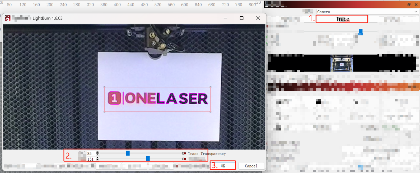
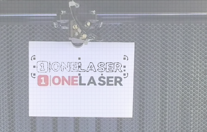
4. After completing the above steps, click “OK” to get the outline pattern of the object.
Important Reminder:
If these steps do not resolve the issue, please submit a support ticket. A technician will then be able to conduct a more in-depth diagnosis.