¶ 1. Introduction: The Hidden Width of a Laser Cut
If you have ever laser-cut a puzzle, press-fit box, or interlocking structure and found that the parts no longer fit as designed, you have encountered kerf — the invisible material loss created during cutting.
Although laser beams are highly precise, they are not infinitely thin. Every laser cut removes a narrow strip of material, typically 0.05–0.25 mm, depending on material type, thickness, and processing parameters.
This removed width is called kerf, and ignoring it leads to cumulative dimensional errors.
Kerf compensation is the practice of adjusting the cutting path or design geometry to offset this loss, ensuring that final parts match their intended dimensions.
¶ 2. What Is Kerf and Why It Exists
Kerf is the width of material that is vaporized, melted, or burned away as the laser passes through the workpiece. It exists for two main reasons:
The laser beam has a finite focal spot diameter
Heat spreads beyond the beam center, forming a heat-affected zone (HAZ)
Typical kerf values vary by material and laser type:
Material (Thickness) |
Laser Type |
Typical Kerf (mm) |
Acrylic (3 mm) |
CO₂ |
0.10–0.20 |
Plywood (3 mm) |
CO₂ |
0.15–0.25 |
Stainless Steel (1 mm) |
Fiber |
0.05–0.10 |
MDF (4 mm) |
CO₂ |
0.20–0.30 |
In thicker materials, kerf is often tapered — wider at the top and narrower at the bottom — due to beam divergence and focal depth limitations.
¶ 3. Why Kerf Compensation Is Essential
For decorative cutting, small dimensional losses may be tolerable. However, in press-fit designs, mechanical assemblies, or stacked structures, kerf quickly becomes critical.
Example:
If each joint loses 0.2 mm and a design includes ten interlocking features, the accumulated error reaches 2 mm — enough to cause loose joints or assembly failure.
Kerf compensation ensures:
Accurate final dimensions
Tight, predictable fits
Reduced rework and material waste
¶ 4. Factors That Affect Kerf Width
¶ 4.1 Material Properties
Dense materials (metal, glass) → narrower kerf
Porous materials (wood, acrylic) → wider kerf due to heat spread
¶ 4.2 Laser Power and Speed
Higher power or slower speed → wider kerf
Lower power or faster speed → narrower kerf (with risk of incomplete cutting)
¶ 4.3 Focus Position
Focus above surface → wider top kerf
Focus below surface → wider bottom kerf
Focus at mid-thickness → most balanced kerf
¶ 4.4 Air / Gas Assist
Strong air assist cools the cut and narrows kerf
Oxygen increases kerf via oxidation
Nitrogen produces cleaner, smaller kerf edges
¶ 5. How to Measure Kerf Accurately
Before applying compensation, kerf must be measured under real cutting conditions.
Simple test method:
Design a square (e.g., 20 × 20 mm) and a matching frame
Cut both using standard settings
Measure the cut square and hole with calipers
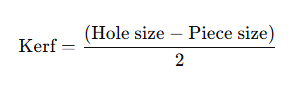
Calculate kerf:
Example:
Design: 20.00 mm
Hole: 20.30 mm
Square: 19.70 mm
Kerf = (20.30 − 19.70) / 2 = 0.30 mm
¶ 6. Applying Kerf Compensation in Software
¶ 6.1 LightBurn
Cut Settings Editor → Kerf Offset
Apply ± half the measured kerf
Preview to confirm offset direction
¶ 6.2 RDWorks / EZCAD
Use Path Offset or Minimum Power Offset
Confirm whether positive values offset inward or outward
¶ 6.3 CAD-Based Workflows
Offset geometry manually
Use parametric variables for material-specific kerf values
¶ 7. Common Kerf-Related Issues
Problem |
Likely Cause |
Solution |
Loose joints |
Undercompensation |
Re-measure kerf |
Parts too tight |
Overcompensation |
Reduce offset |
Uneven kerf |
Incorrect focus |
Refocus mid-thickness |
Inconsistent fit |
Airflow variation |
Stabilize air assist |
¶ 8. Case Example: Acrylic Press-Fit Box
Material: 3 mm acrylic
Laser: 60W CO₂
Measured kerf: 0.15 mm
Applied offset: ±0.075 mm
Result:
Clean press-fit joints with no glue required — tight, accurate, and repeatable.
¶ 9. Conclusion: Small Numbers, Big Impact
Kerf compensation is a small adjustment with a large effect. Ignoring a 0.1 mm material loss can compromise entire assemblies, while properly managing kerf enables precision, repeatability, and professional-grade results.
Precision in laser cutting is not just about power or optics — it is about understanding and controlling material removal.