¶ Drawing dimensions do not match actual dimensions
This guide explains how to correct size discrepancies between your design file and the actual processed result. If a 100mm × 100mm square is cut but the physical measurement differs from the drawing, the issue is typically caused by incorrect motor step parameter settings.
By calibrating the X-axis and Y-axis step values in your control software, you can restore machining accuracy.
¶ Problem Description
In the actual machining process, if you find that the machined dimensions do not match the drawing dimensions, for example, the drawing requires the machining of a 100mm x 100mm square, but the actual machined dimensions are not so, then it is likely to be due to the incorrect setting of the motor's step parameter.
¶ Required Tools
- RDworksV8 or Lightburn or MakerBoost
- High-precision ruler
¶ Operation Guide
Draw a rectangle with dimensions of 300mm × 200mm and process the graphic.
Measure the actual dimensions of the X-axis (length direction) and Y-axis (width direction) of the processed rectangle using an accurate measuring tool.
If the dimensions of the rectangle do not correspond to the dimensions of the drawing, do the following:
¶ If using RDWorksV8
Click File >> Vendor settings >> Enter the password: RD8888 to enter the manufacturer's parameter settings >> Select “Motor” >> Click “Read”.
After reading the parameters, click “Mark 1” and select the axial parameter (X-axis or Y-axis) to be adjusted. If the actual dimensions of both X-axis and Y-axis do not meet the requirements, it is necessary to calibrate the two axes separately.
- Graphic length: Enter the dimensions of the drawing.
- Measurement length: input the actual measurement size.
- Click “OK” and “Write ” when finished.
After completing the setup, processing a 300mm × 200mm rectangle, and again measure his actual size.
Note:
If the size of the rectangle and the drawing size or inconsistent, it is necessary to repeat the above operation until the actual size and the drawing size of the same
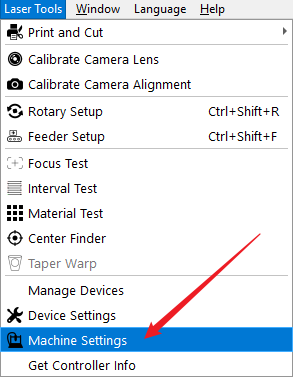
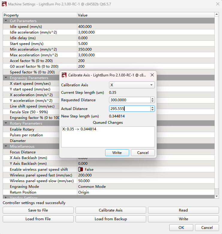
¶ If using Lightburn
Click Laser Tools >> Machine Settings >> Calibrate Axis.
Select the X axis, and input the measured values into the corresponding fields for Requested Distance (e.g. 300mm) and Actual Distance (the measured value). The software will automatically calculate the new step distance coefficient. Click Write to save the new setting to the machine. Repeat the same steps for the Y axis.
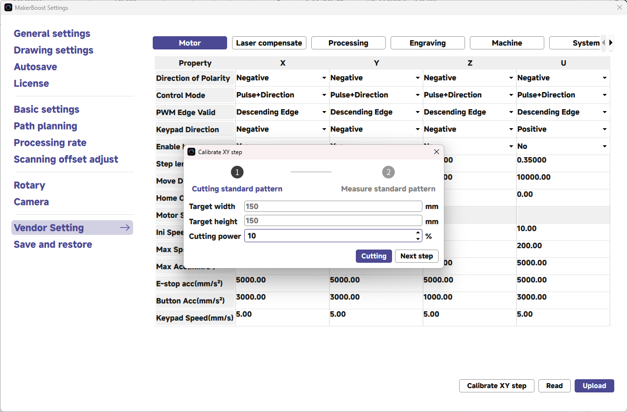
¶ If using MakerBoost
Click Settings >> Vendor Setting and enter the password: TL9501 >> Calibrate XY step.
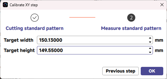
In the new window, input the cutting power and click the Cutting button. The machine will automatically cut a square.
Measure the actual width and height of the processed square. Input these values into the corresponding fields. The software will automatically calculate the new step distance coefficient.
You may need to perform this calibration one or more times to obtain more accurate parameters.
Important Reminder:
If these steps do not resolve the issue, please submit a support ticket. A technician will then be able to conduct a more in-depth diagnosis.