¶ How to Adjust the Backlash Parameters
Backlash and scan offset issues can cause misaligned lines, blurred engraving, and uneven results. This guide explains how to adjust backlash parameters using LightBurn, including preparation, test file setup, scan offset tuning, and verification to achieve clean, accurate engraving.
¶ Note
The reverse clearance of the equipment has been adjusted to the best engraving effect before leaving the factory. Please do not adjust it at will unless you encounter special circumstances.
At the same time, the engraving reverse clearance parameters tested by the manufacturer are on the aluminum foil sheet that comes with the machine, which can be directly filled in.
¶ 1. Preparation
¶ ① Material Preparation
Aluminum foil pieces
Magnifier ×1
One Laser X series device ×1
Computer ×1
¶ ② Debug Software
LightBurn
¶ 2. Adjustment Steps
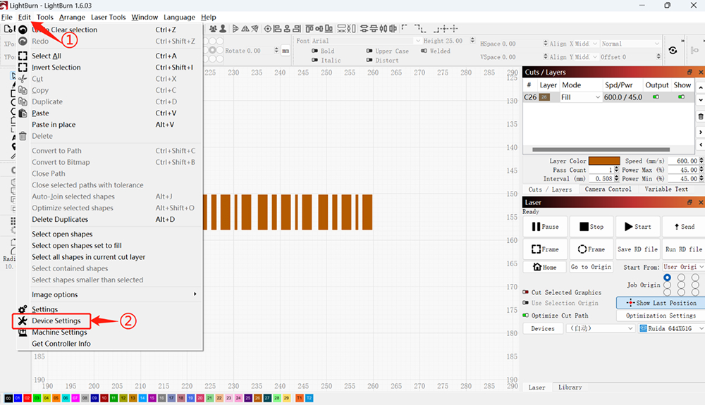
¶ ① Open the Software
Click Edit → Device Settings to enter the device settings interface.
¶ ② In the Machine Settings Interface
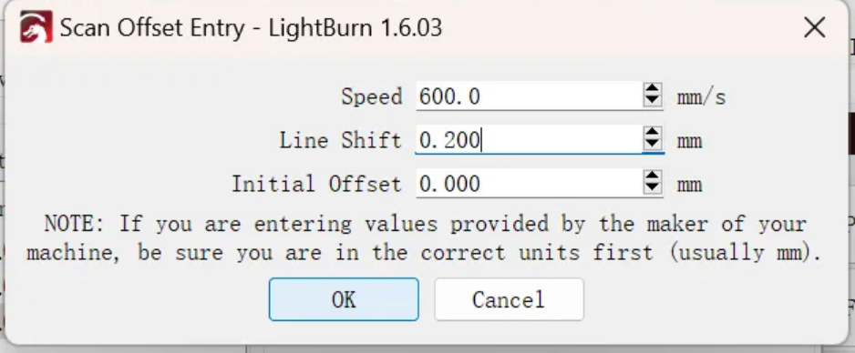
a. Click Basic Settings, check Enable Scanning Offset Adjustment, and click Add to add a speed parameter
(set according to personal processing needs)
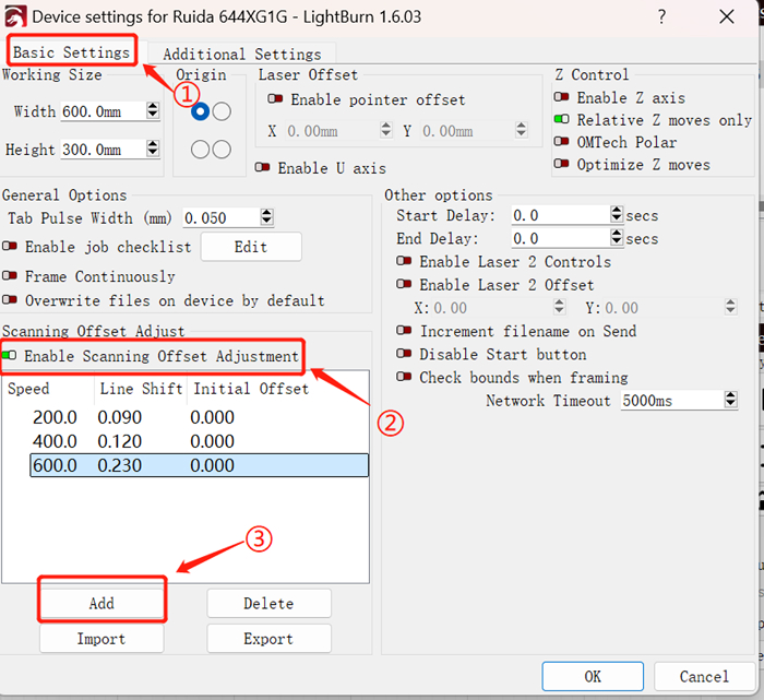
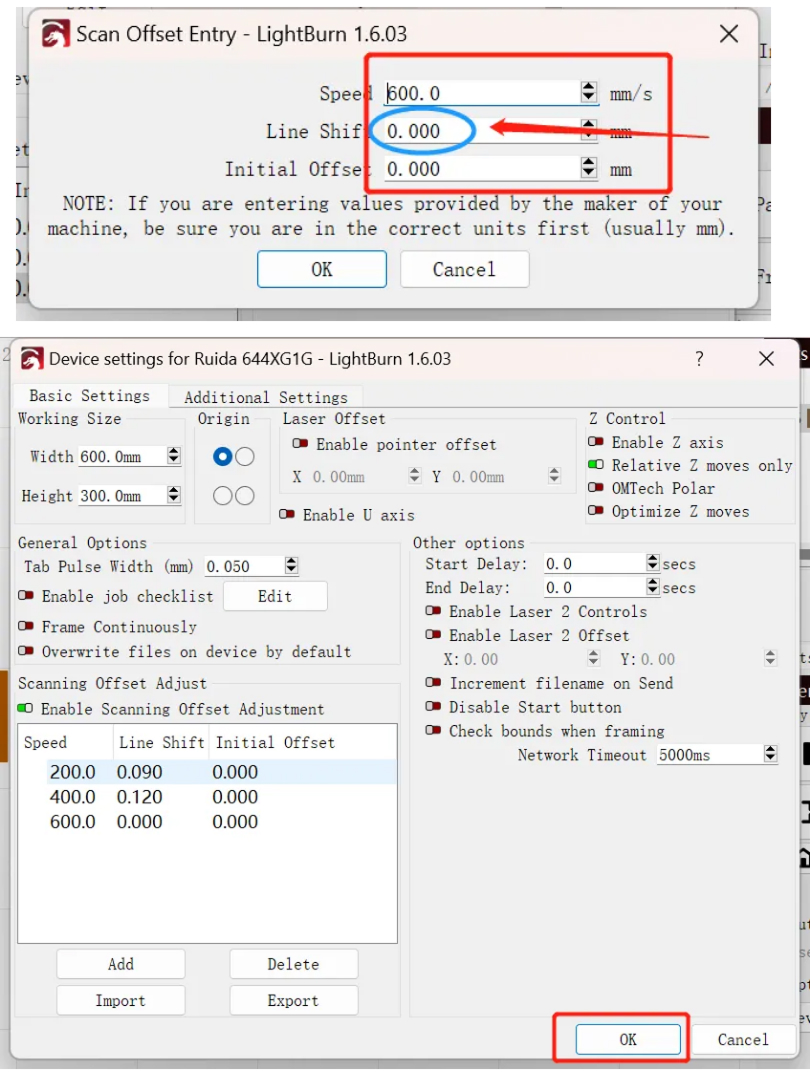
b. First fill in the speed parameter 600 (according to personal needs).
Do not fill in the offset parameter.
Set Line Shift = 0, then click OK after completing the settings.
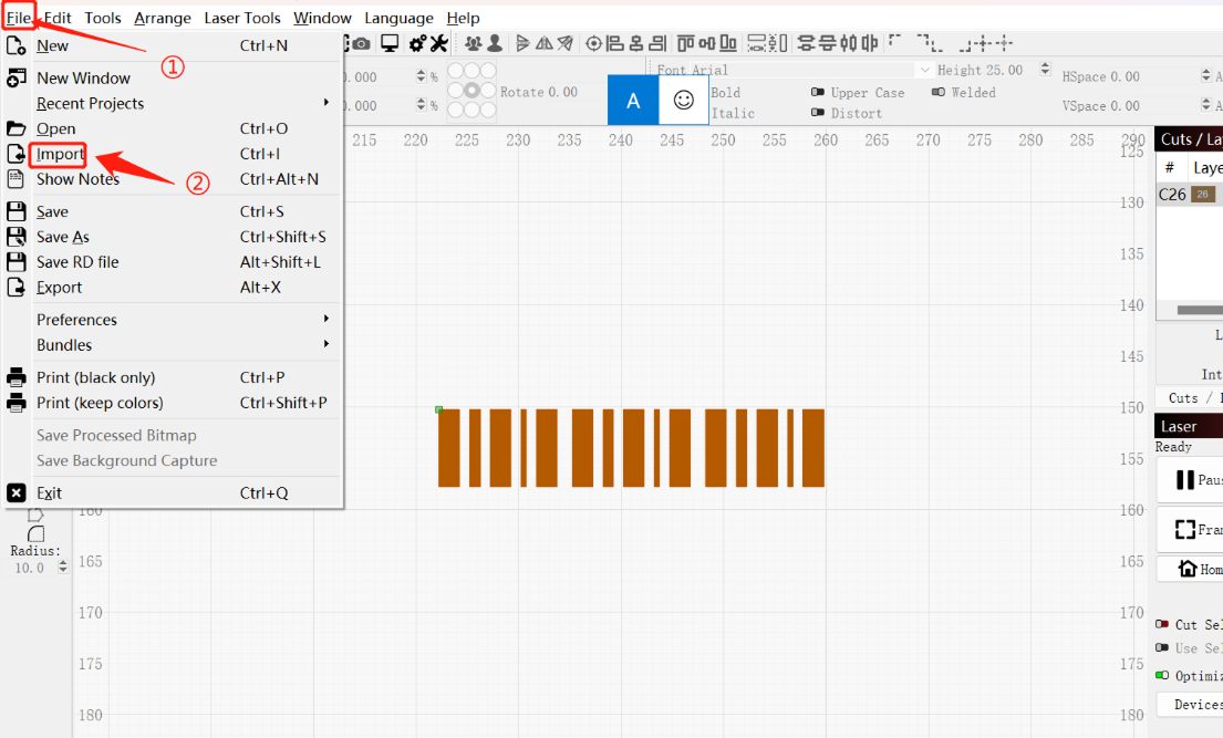
¶ 3. Importing Test Files
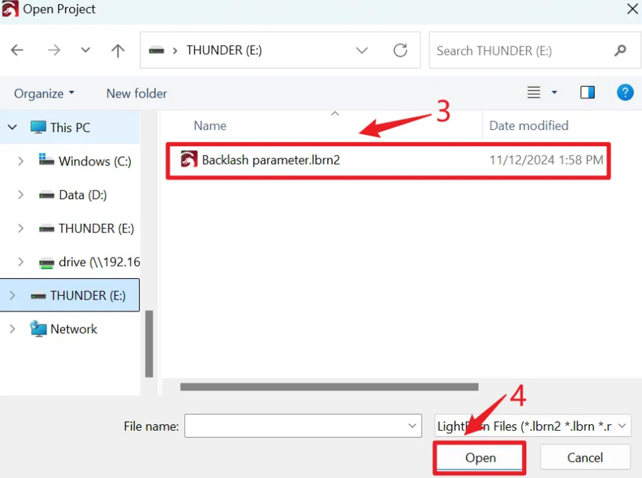
a. Click File → Import, select the file, and click Open
Note: This test file needs to be provided by the manufacturer’s technical staff.
¶ 4. Set Processing Parameters
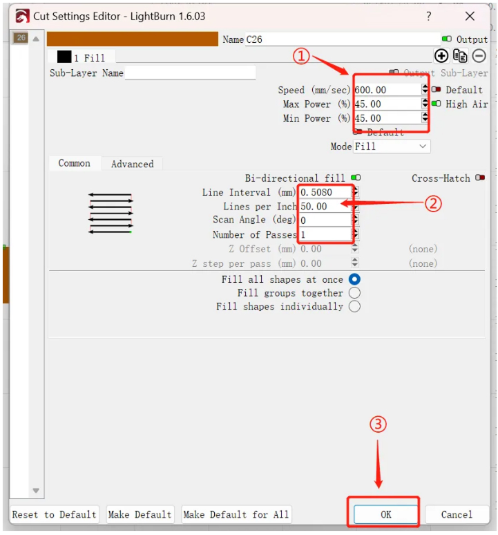
a. Double-click the processing parameter status bar to set the engraving parameters.
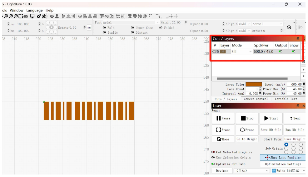
b. Set:
Engraving speed: 600 mm/s
Line distance (Lines per Inch): 50
After setting, click OK to confirm.
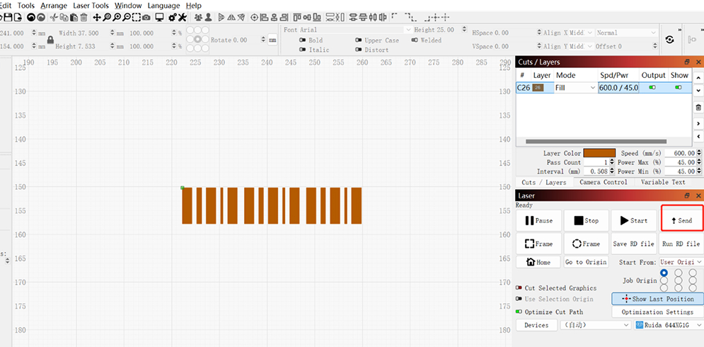
c. Upload the file to the device for processing.
¶ 5. Equipment Processing
a. Place the aluminum foil on the platform, adjust the focal length, then position and process along the border.
Speed: 600 mm/s
Offset value: 0
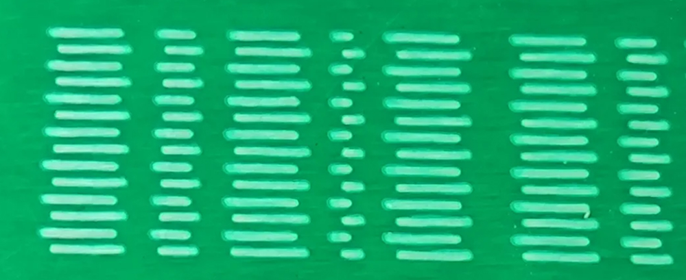
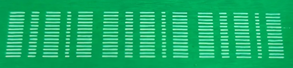
b. As shown in the picture, the line offset is particularly obvious and will affect the actual engraving result.
From top to bottom:
Odd-numbered line segments are used as reference
Even-numbered line segments are biased to the right
You need to increase the offset parameter to make the lines basically overlap.
¶ 6. Changing the Offset Parameters
a. Follow the above steps to fine-tune the offset parameters between 0.05 – 0.3 mm.
During the adjustment process, continuously observe the engraving effect to ensure the best setting.
b. After increasing the offset, the lines are roughly aligned, but the even-numbered line segments are slightly biased to the left.
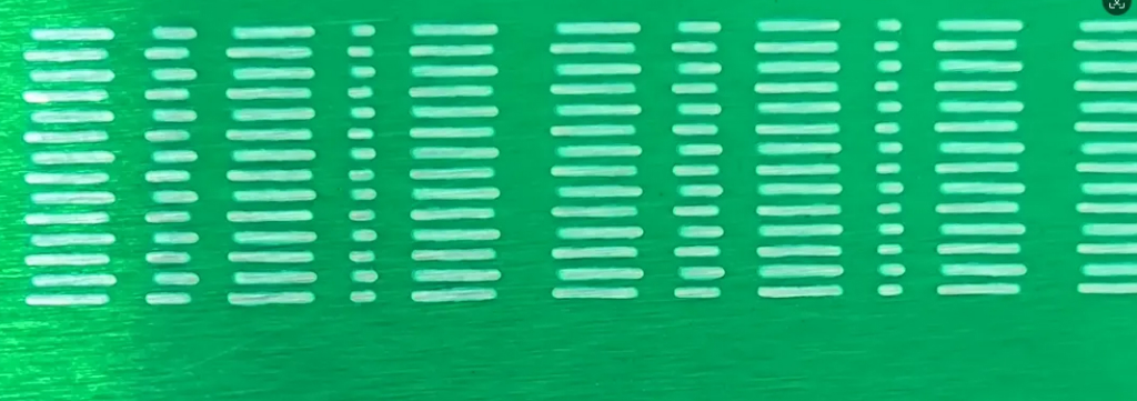
At this time, slightly reduce the offset until all lines are basically aligned.
c. Reduce the offset parameter, save, and upload the drawing again.
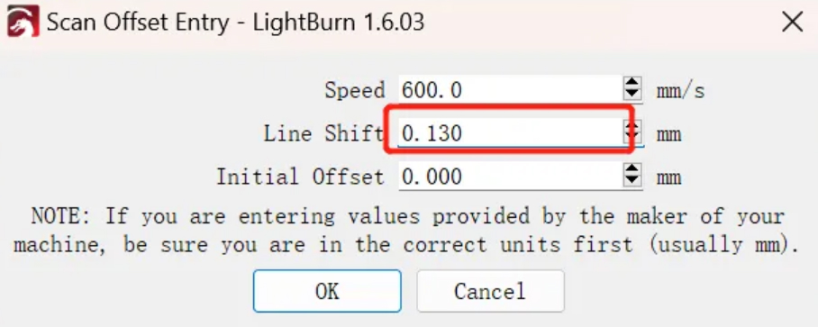
After adjustment, upload the drawing again for processing.
¶ Result
It can be seen that the odd and even line segments basically overlap, and the adjustment is completed.