¶ Beam Path Misalignment - X Series
¶ Problem Description
- Regardless of the position on the workbed, the processing results in the far areas (further away from the origin) are consistently worse than those in the near areas. This manifests as the kerf widening, the cut becoming gradually shallower, or the laser failing to cut through the material entirely.
- When checking beam alignment by moving the laser head to the four corners of the workbed, the burn marks left on the tape do not coincide.
¶ Cause
Beam path misalignment can be caused by many factors, including:
- The angle of a mirror mount was accidentally shifted during the cleaning of the mirrors.
- Shipping and vibration caused the optics to shift out of alignment.
¶ Solution
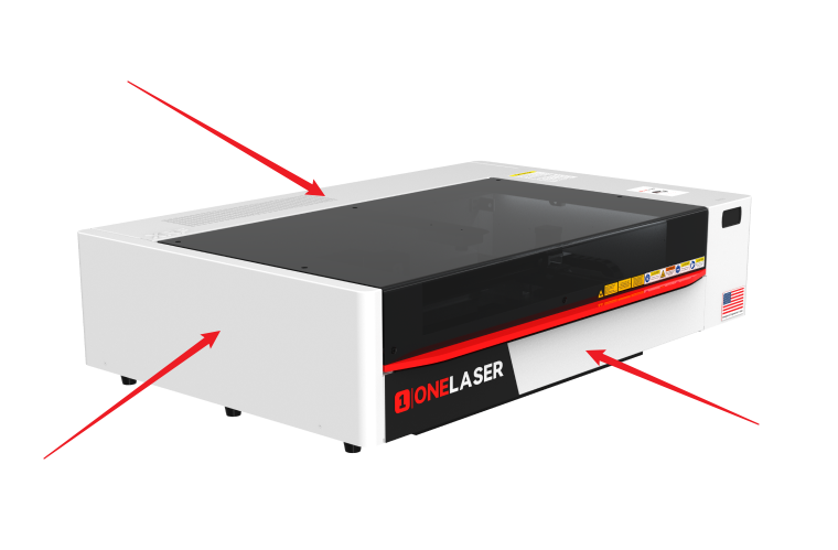
Use an M2 hex wrench to remove the front door cover, back door cover, and left side panel. This provides visibility and access for adjusting the beam path from all positions.
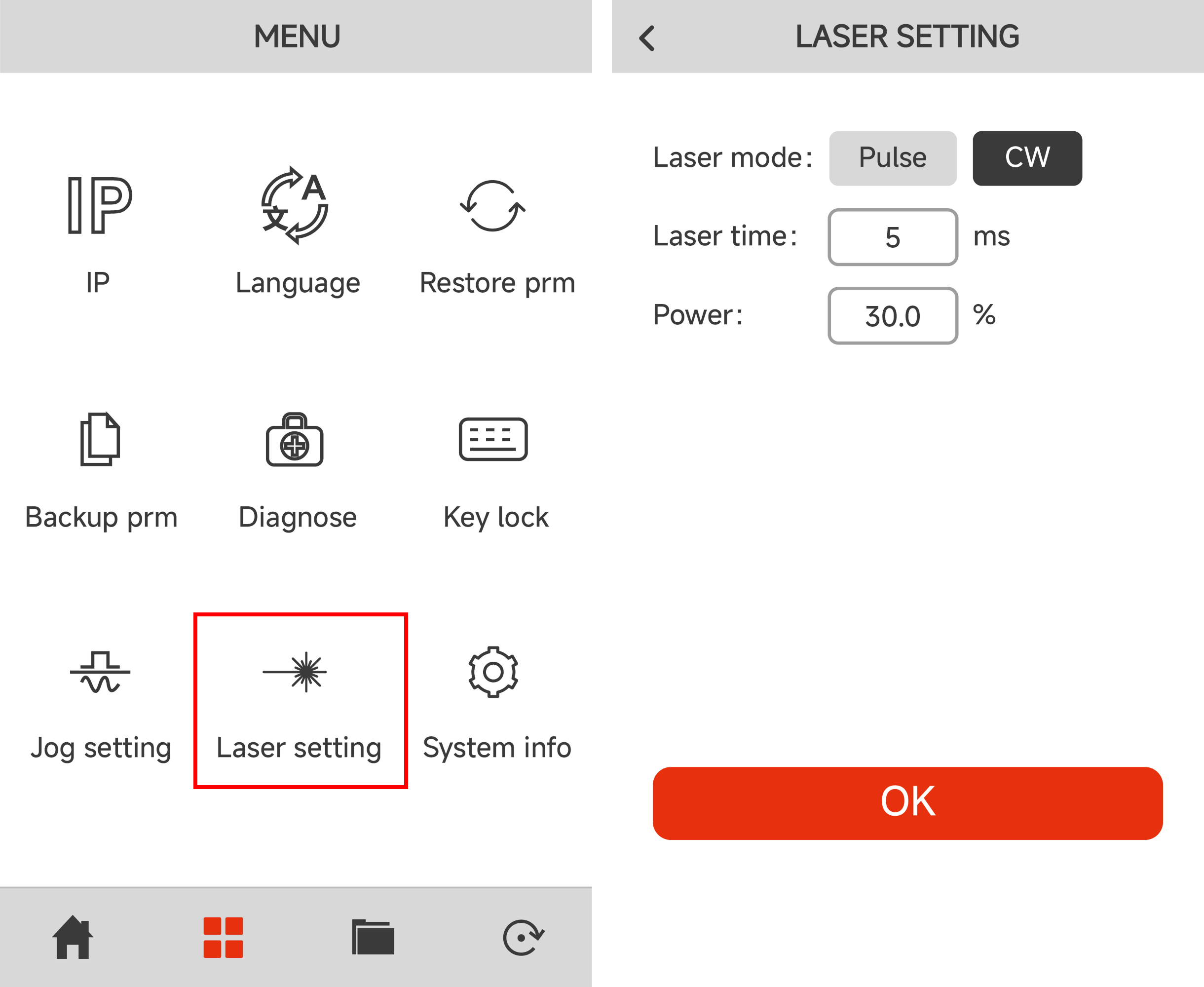
The alignment process requires using the Pulse function. Set the pulse parameters on the control panel: Click Laser Setting on the Menu page. Set the parameters to CW, 5 ms, and 30% power. Then click OK to return to the main page.
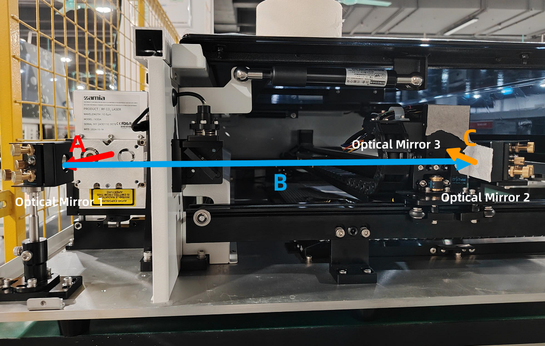
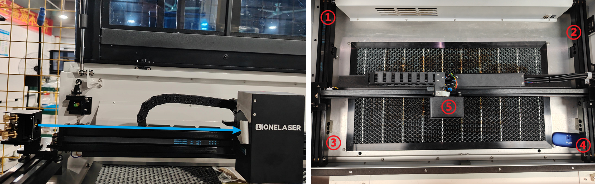
The laser beam path and the corresponding mirror assemblies are identified in the figure below:
¶ Step 1. Adjusting Optical Path A&B
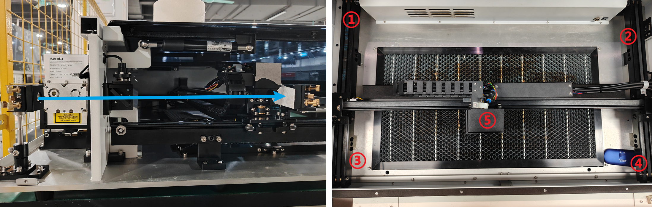
Place tape over the aperture of Optical Mirror 2. Move the laser head to the top-left and bottom-left positions of the platform (positions ① and ③ in the diagram).
Pulse the laser at both positions and observe the burn marks on the tape.
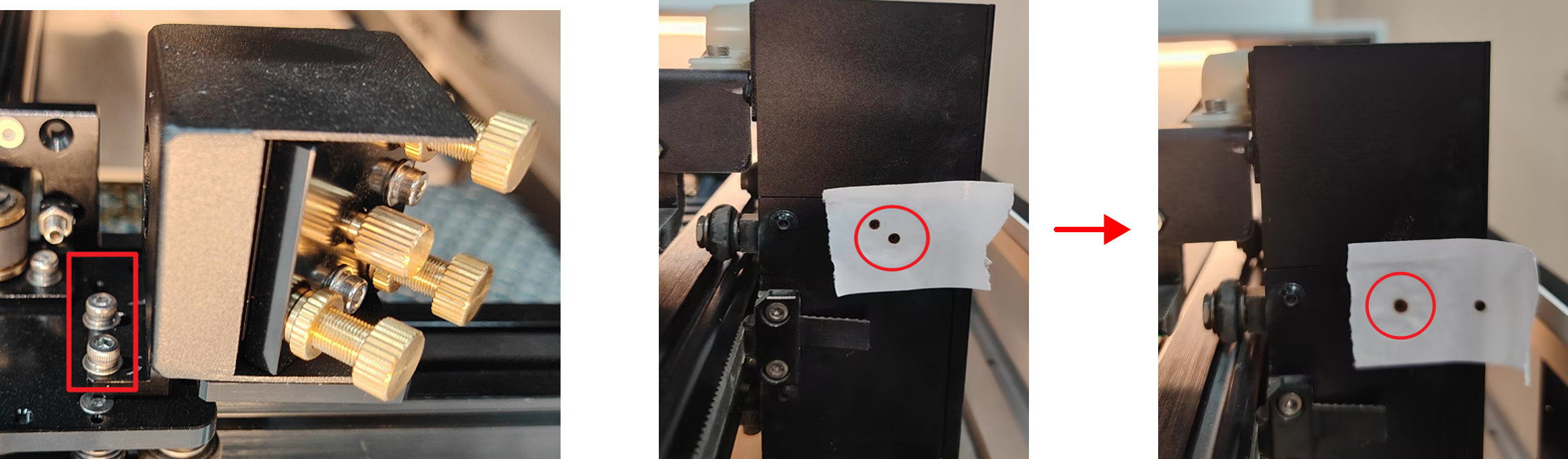
If the burn marks are significantly offset between the two positions, you need to adjust the mounting bracket of Optical Mirror 1 to bring the spots into approximate coincidence:
Loosen the screws on the black mirror mount bracket. As you re-tighten the screws, slightly adjust the mirror frame on the bracket. Observe the direction the laser spot moves as you tighten and push the frame slightly in the opposite direction.
First, tighten one screw, check for deviation, then tighten the second screw. Continue this adjustment until the burn marks are roughly overlapping.

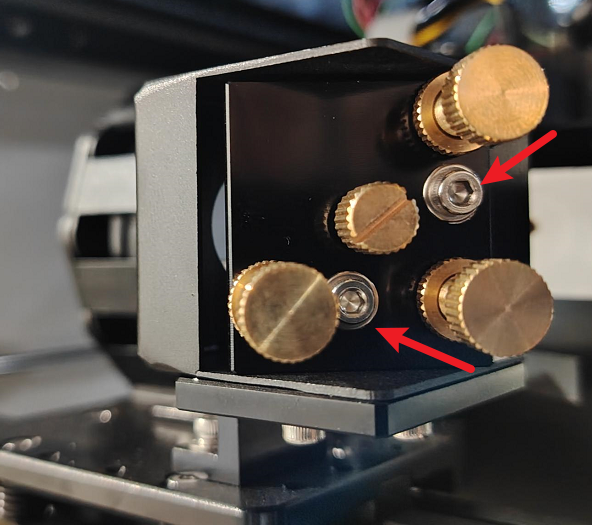
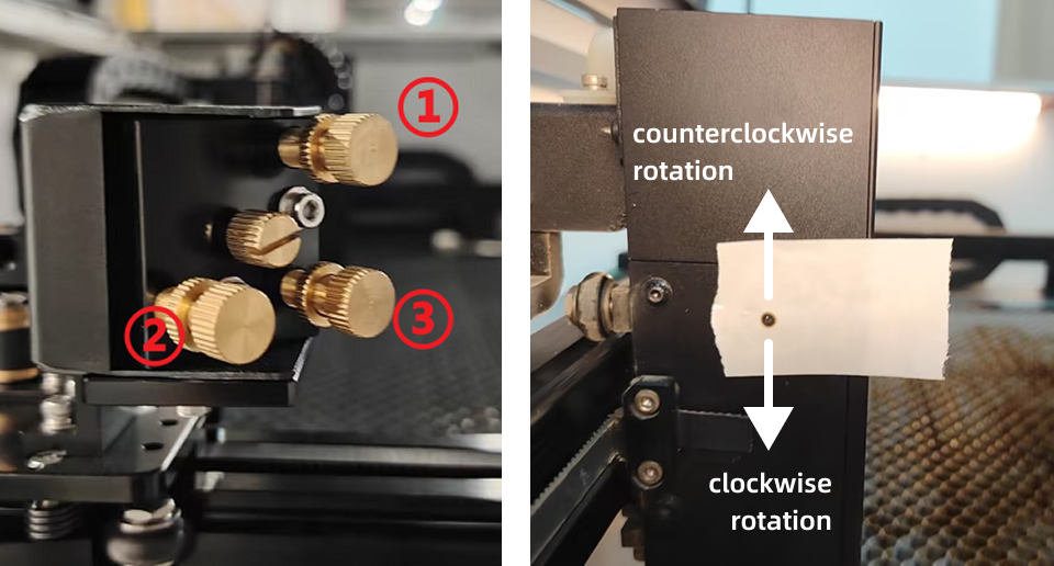
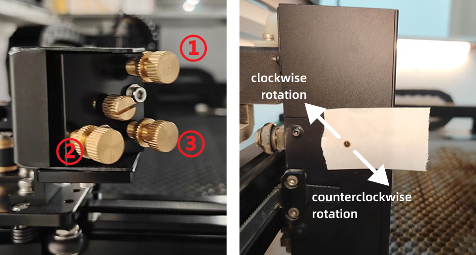
Use an M2.5 hex wrench to slightly loosen the silver-white lock nuts on the Optical Mirror 1 mount. Rotate the gold screws according to the actual position of the burn marks:
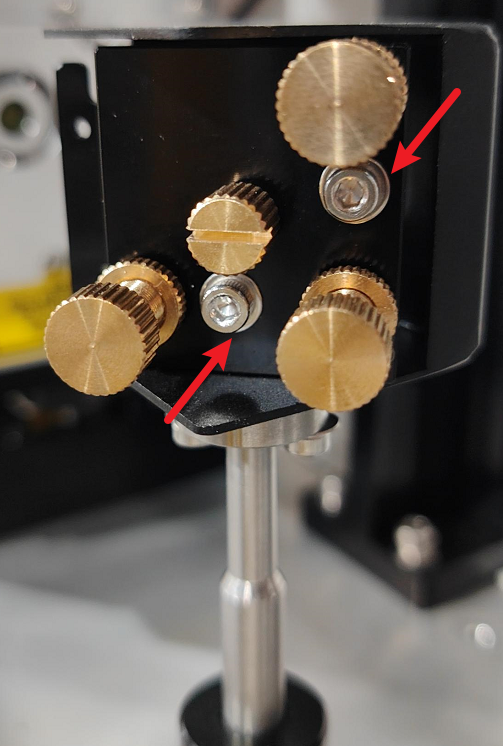
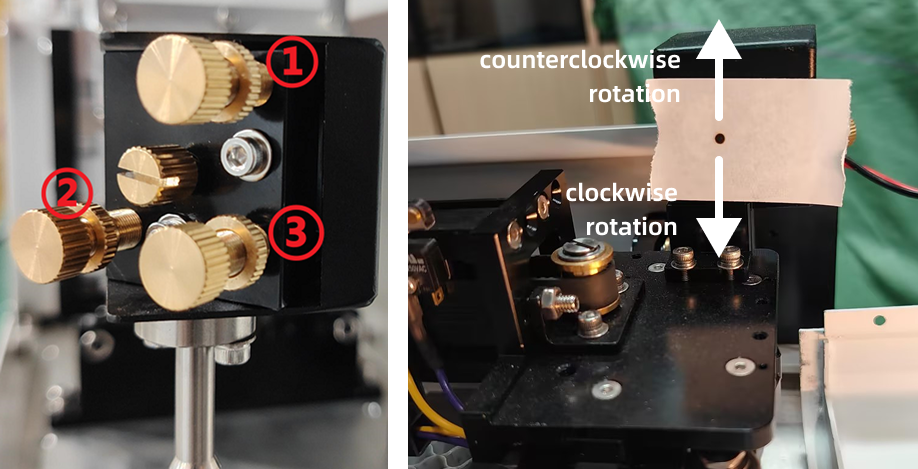
- Screw #1: Rotates clockwise to move the beam down; counter-clockwise moves the beam up.
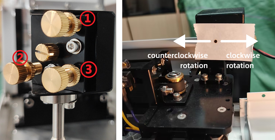
- Screw #2: Rotates clockwise to move the beam right; counter-clockwise moves the beam left.
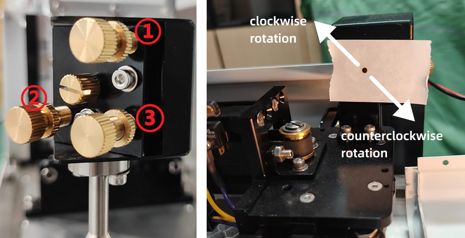
- Screw #3: Rotates clockwise to move the beam up and left; counter-clockwise moves the beam down and right.
Adjust these three screws until the front and rear laser spots coincide at the exact same point (observed via the burn marks).
Reminder: Once coincidence is achieved, ensure all screws on the mirror mount are securely locked.
¶ Step 2. Adjusting Optical Path C
Place tape over the aperture of Optical Mirror 3. Move the laser head to the top-left and top-right positions of the platform (positions ① and ② in the diagram). Pulse the laser at both positions and observe the burn marks on the tape.
If the burn marks are significantly offset between the two positions, you need to adjust the mounting bracket of Optical Mirror 2 to bring the spots into approximate coincidence:
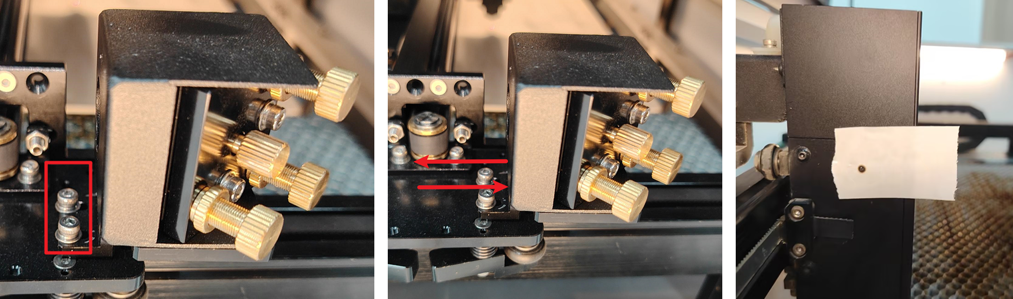
Use an M2.5 hex wrench to loosen the two fixed screws shown in the diagram.
Gently pivot the second mirror frame until the burn marks on the tape from positions ① and ② are largely overlapping. Lock the screws once overlapping.
Use an M2.5 hex wrench to slightly loosen the silver-white lock nuts on the Optical Mirror 2 mount. Rotate the gold screws according to the actual position of the burn marks:
- Screw #1: Rotates clockwise to move the beam down; counter-clockwise moves the beam up.
- Screw #2: Rotates clockwise to move the beam right; counter-clockwise moves the beam left.

- Screw #3: Rotates clockwise to move the beam up and left; counter-clockwise moves the beam down and right.
Adjust these three screws until the laser spots from all four test positions (implied: ①, ②, ③, ④) coincide at the exact same point (observed via the burn marks).
Reminder: Once coincidence is achieved, ensure all screws on the mirror mount are securely locked.
¶ Step 3. Adjusting the Beam to the Center Point
If the laser spot has a horizontal offset from the center point, you need to adjust the Optical Mirror 2 mount:
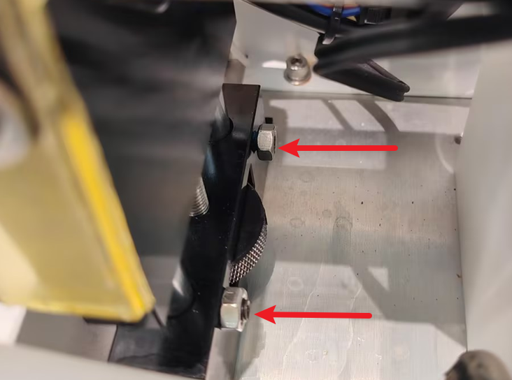
Use an M2.5 hex wrench to slightly loosen the two silver lock nuts shown in the diagram.
Gently push the second mirror frame: if the spot is offset to the left, move the frame slightly to the right; if the spot is offset to the right, move the frame slightly to the left, until the spot is centered.
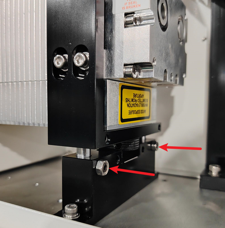
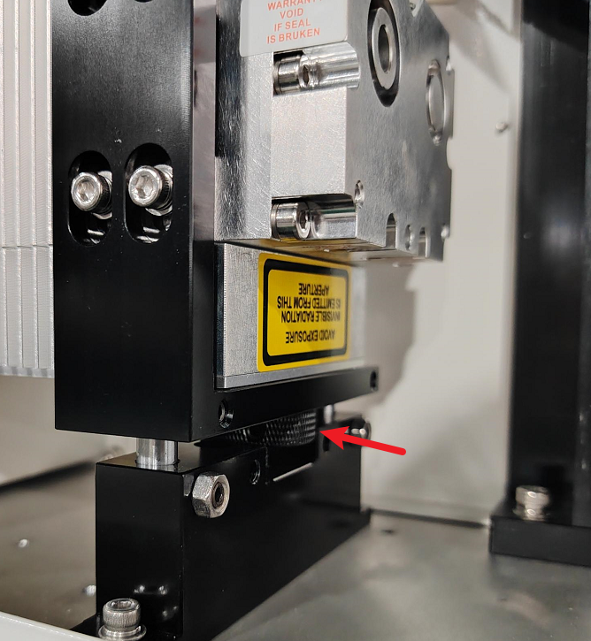
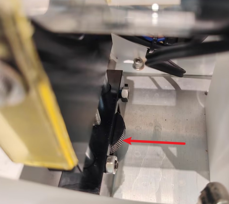
If the laser spot has a vertical offset from the center point, you need to adjust the height of the laser tube:
Use an M2.5 hex wrench to loosen the two screws on the laser mount base.
 |
 |
|
RF Tube |
Glass Tube |
Turn the illustrated knob: rotating clockwise raises the spot; rotating counter-clockwise lowers the spot, until the spot is at the center point. Tighten the screws once the adjustment is complete.
Reminder: The laser tube must remain level, and both screws must be securely locked.
 |
 |
|
RF Tube |
Glass Tube |
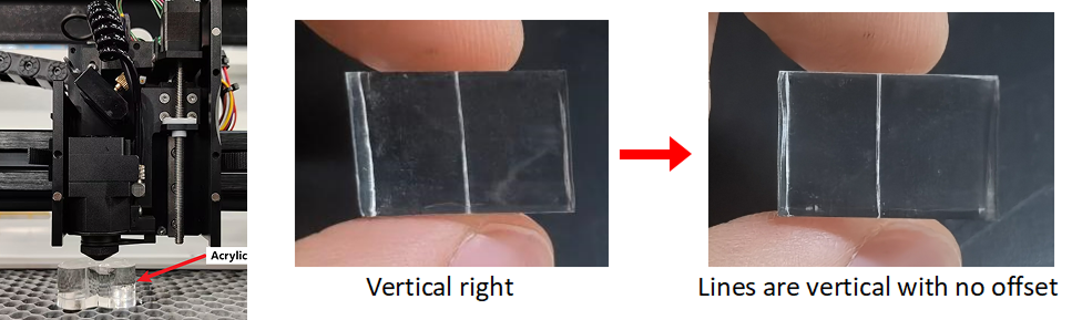
¶ Step 4. Adjusting the Laser Head Verticality
Place a piece of acrylic directly beneath the laser head cone. Follow the pulse setting steps outlined previously, but change the pulse power to 60%. Return to the main page and click the Pulse button.
Check the path of the laser strike through the acrylic to see if the penetration path is perfectly vertical.
- If the verticality is tilted to the left, you need to raise the laser tube slightly.
- If the verticality is tilted to the right, you need to lower the laser tube slightly.
Reminder: After completing all adjustments, please ensure that all securing screws are tightened, and that all door covers are reinstalled and their screws are secured.
Important Reminder:
If these steps do not resolve the issue, please submit a support ticket on ZOHO: https://zohodesk.1laser.com/portal/en/newticket. A technician will then be able to conduct a more in-depth diagnosis and resolve your problem.