¶ 1. Introduction: When a Small Change Causes System-Level Problems
In real-world usage, users sometimes attempt to solve poor cutting performance—especially caused by insufficient air assist—by modifying the optical setup.
One common practice is:
Installing a 2.5″ focal length lens into a position originally designed for a 2″ lens (i.e., moving the lens closer to the nozzle).
At first glance, this may seem like a harmless adjustment. After all, the lens itself has not changed. However, the resulting issues are often severe and confusing:
Acrylic cuts become wider and rougher
Edges appear frosted or melted
Cutting performance becomes inconsistent depending on direction
Shapes no longer close properly, resembling backlash errors


These symptoms are frequently misdiagnosed as mechanical problems. In reality, they originate from a much earlier stage in the system:
The optical geometry has been fundamentally altered.
¶ 2. What Actually Changed: The Optical System Geometry
It is important to clarify that:
You did not change the focal length—you changed the relative position of the lens within the optical system.
In a properly designed laser head:
A 2.5″ lens is paired with a specific tube length and nozzle geometry
The system ensures that the laser beam fully converges before or just after exiting the nozzle
The focal point is located below the nozzle tip, inside or near the material surface
When the lens is moved downward into a 2″ position:
The convergence process is interrupted
The focal point shifts upward
The beam reaches the nozzle before it has fully narrowed
¶ 3. Why the Beam Cannot Pass Through the Nozzle Properly
¶ 3.1 The Beam Is Physically Too Large at the Nozzle
A 2.5″ lens produces a more gradual convergence compared to a 2″ lens. This means the beam diameter remains relatively large until it gets closer to the focal point.
By placing the lens closer to the nozzle:
The beam arrives at the nozzle earlier in its convergence path
Its diameter may exceed the nozzle aperture
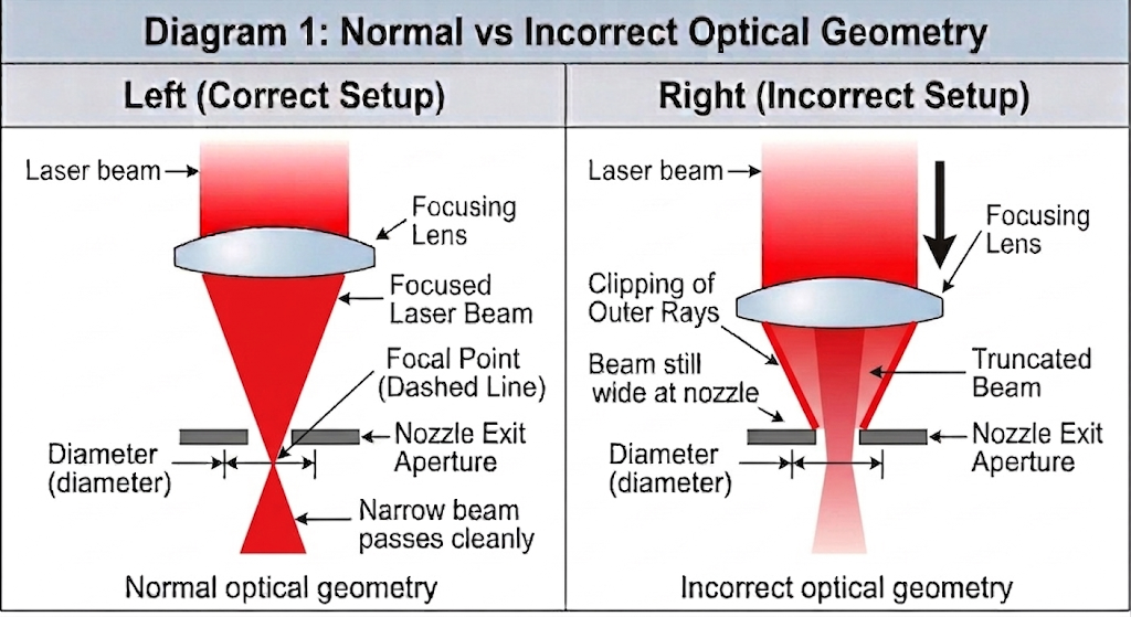
As a result:
A portion of the laser beam is physically blocked by the inner wall of the nozzle.
¶ 3.2 The Nozzle Acts as an Optical Aperture
Under these conditions, the nozzle is no longer just guiding airflow. It becomes an unintended optical limiting aperture.
This has several consequences:
The outer portion of the beam is cut off
The original Gaussian energy distribution is distorted
The beam profile becomes asymmetric and unstable
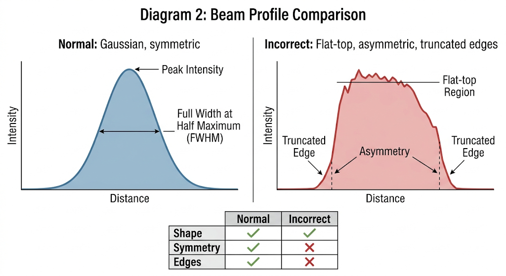
Instead of a clean, focused spot, you now have:
A partially clipped, irregular energy distribution
¶ 3.3 Alignment Alone Cannot Solve the Problem
Even if the optical alignment is perfectly centered, the issue persists.
This is because:
The problem is not beam misalignment, but beam size mismatch with the mechanical structure.
¶ 4. Why Acrylic Cutting Quality Degrades Significantly
Materials like PMMA (acrylic) are highly sensitive to energy distribution and airflow conditions.
¶ 4.1 Loss of Energy Density
A proper laser cut depends on concentrating energy into a very small spot. When the beam is clipped:
The central intensity decreases
Energy is redistributed toward the edges
This reduces the laser’s ability to cleanly vaporize or melt through the material.
¶ 4.2 Increased Thermal Spread
Instead of cutting sharply, the laser begins to heat a wider area:
The material softens over a larger region
The kerf (cut width) increases
Edges become rounded rather than sharp
¶ 4.3 Poor Material Removal
Because the beam is distorted and airflow is no longer aligned:
Molten material is not efficiently expelled
Residue accumulates in the কাট zone
Secondary heating occurs
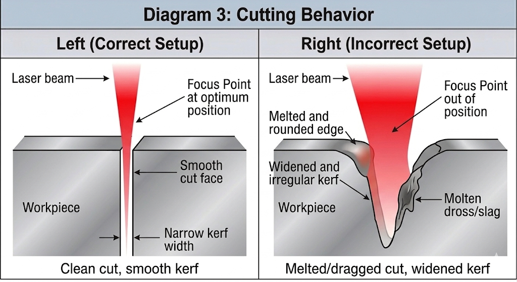
¶ Final Result
Wider kerf
Frosted or white edges
Melt buildup and debris
Reduced clarity in acrylic
¶ 5. Why It Causes “Backlash-Like” Motion Errors
This is one of the most misunderstood effects.
¶ 5.1 The Machine Has Not Changed—The Load Has
Mechanical backlash is typically a fixed property of the motion system. However, in this case:
The cutting resistance becomes variable and direction-dependent
¶ 5.2 Cutting Becomes Dragging
Because the beam no longer cleanly penetrates the material:
Some regions are fully cut
Others remain partially connected
As the laser head moves, it must physically overcome these connections.
¶ 5.3 Direction-Dependent Resistance
In the forward direction, the material is preheated and easier to cut
In the reverse direction, the head encounters uncut material and accumulated debris
This creates uneven resistance depending on motion direction.
¶ 5.4 How This Mimics Backlash
When reversing direction:
The drive system (belt or leadscrew) first absorbs the load
Then begins actual motion
This delay appears as:
Offset paths
Misaligned endpoints
Distorted shapes (e.g., circles becoming oval)
¶ Key Insight
This is not true backlash—it is load-induced positional lag.
¶ 6. Additional Issues Caused by This Setup
¶ 6.1 Nozzle Damage
Since part of the beam hits the nozzle:
Localized heating occurs
Material buildup accelerates
The nozzle may deform over time
¶ 6.2 Lens Contamination and Damage
Reflected and scattered energy can:
Return toward the lens
Damage coatings
Increase contamination rates
¶ 6.3 Unstable Focus Behavior
Users often report that:
There is no clear “best focus” point
Results vary unpredictably
This happens because:
The effective focal structure has already been disrupted.
¶ 6.4 Inconsistent Cutting Performance
Different directions produce different results
Identical parameters no longer yield repeatable outcomes
¶ 7. Comparison Table
Parameter |
Correct Setup (2.5″ Proper Position) |
Incorrect Setup (2.5″ in 2″ Position) |
Beam at Nozzle |
Fully converged or near focus |
Still wide and unconverged |
Energy Distribution |
Symmetric, Gaussian |
Clipped, distorted |
Cutting Mode |
Clean separation |
Partial melting and dragging |
Kerf Width |
Narrow and consistent |
Wide and irregular |
Edge Quality |
Smooth and clear |
Frosted, rough |
Motion Behavior |
Stable |
Direction-dependent errors |
Focus Stability |
Clear focal point |
Unstable / unclear |
Nozzle Interaction |
Minimal |
Beam hits nozzle walls |
¶ 8. Final Takeaway
Installing a 2.5″ lens in a 2″ position does not simply “shift focus”—it fundamentally disrupts how the laser beam is formed and delivered.
All the observed issues—poor cutting quality, inconsistent results, and apparent backlash errors—can be traced back to one root cause:
The laser beam is being physically clipped before it even reaches the material.
¶ 9. Recommended Solution (Detailed & Practical)
Solving this issue requires restoring the optical system to a physically correct state. Below are practical steps you can follow, including real-world adjustments and trade-offs.
¶ 9.1 Restore the Correct Lens Position
The first and most critical step is to ensure that the lens is installed in the position it was designed for.
A 2.5″ focal length lens is intended to work with a specific optical path length. Moving it closer to the nozzle disrupts where the beam converges.
¶ What you should do:
Reinstall the 2.5″ lens in its original (higher) position
Use a lens tube or holder that matches the focal length
If your machine supports modular heads, switch to a dedicated 2.5″ configuration rather than adapting a 2″ setup
¶ Why this matters:
This ensures that:
The beam has enough distance to fully converge
The focal point is located in the correct working zone
The beam diameter at the nozzle is small enough to pass cleanly
¶ 9.2 Ensure the Beam Fully Passes Through the Nozzle
If restoring the original structure is temporarily not possible, you must ensure that the beam is not physically clipped by the nozzle.
¶ Practical methods:
Option A — Enlarge the nozzle aperture (temporary workaround)
Carefully increase the nozzle hole diameter (e.g., from 1.5 mm → 2.0–2.5 mm)
This allows a wider beam to pass through without being blocked
⚠️ Important considerations:
Use precision drilling or a pre-machined nozzle to maintain symmetry
Avoid rough edges, as they disturb airflow
A larger aperture reduces air velocity, which may affect cutting performance
Option B — Replace with a larger-aperture nozzle
Use a nozzle specifically designed for longer focal length lenses
These nozzles typically have wider openings and longer profiles
Option C — Check beam alignment through the nozzle
Fire a low-power pulse onto tape placed under the nozzle
Ensure the burn mark is perfectly centered and not clipped
¶ Goal:
The beam should pass through the nozzle without touching or being restricted at any point.
¶ 9.3 Ensure the Focal Point Lies Below the Nozzle Exit
Even with correct positioning, improper focus height can still cause instability.
¶ How to verify:
Perform a focus ramp test (inclined plane test)
Identify the point where the kerf is narrowest and most consistent
¶ Target condition:
The focal point should be slightly below the nozzle exit, typically:
At the material surface, or
Slightly inside the material (depending on thickness)
¶ Why this matters:
If the focus is above the nozzle:
The beam is still converging inside the nozzle
Beam diameter increases at the exit
Cutting efficiency drops
¶ 9.4 Address Airflow Issues Separately (Do Not “Hack” the Optics)
Many users make this modification because of insufficient air assist. However, optical misconfiguration is not a valid solution to airflow problems.
¶ Improve airflow properly:
1. Increase airflow rate (not just pressure)
Use a higher flow-rate air pump or compressor
Ensure stable and continuous airflow
2. Optimize air path
Use wider air tubing to reduce flow resistance
Minimize sharp bends and leaks
Check all connectors for sealing
3. Match nozzle design to application
Small aperture → higher air velocity (good for engraving)
Larger aperture → higher flow volume (better for cutting thick materials)
4. Keep the nozzle clean
Remove debris, carbon buildup, or melted residue
Even small obstructions can disrupt airflow symmetry
¶ 9.5 If You Must Use This Setup (Not Recommended)
If the modified configuration cannot be avoided, you should at least stabilize it as much as possible.
¶ Compensations:
Increase nozzle diameter to prevent beam clipping
Lower expectations for cutting precision
Reduce speed to compensate for lower energy density
Increase air assist to help remove melt
¶ ⚠️ Trade-offs:
Wider kerf
Reduced edge quality
Higher thermal damage
Less repeatable results
¶ Final Recommendation
The correct approach is always to match optical design, airflow, and mechanical structure, rather than forcing one system to compensate for another.