¶ Control Card Replacement
This guide provides a step-by-step walkthrough for control card replacement in laser machines. It covers safety precautions, required tools, enclosure removal, control board disassembly, proper cable handling, and reinstallation to ensure stable operation and prevent wiring errors.
¶ Note:
Before unplugging the cable, please take a photo to record the connection status to prevent incorrect wiring during reinstallation.
Keep the removed screws in a safe place to prevent loss.
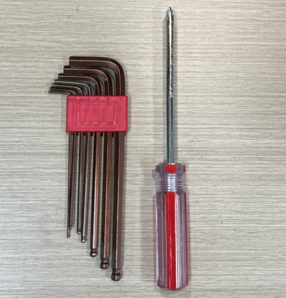
¶ Tools Required
Hex wrenches (M2 & M3), Phillips screwdriver
¶ 1. Removing the Machine Enclosure
① Ensure that the device power is disconnected.
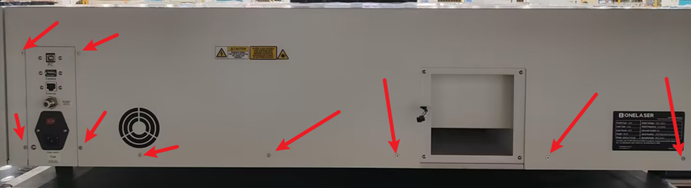
② Use the M2 hex wrench to remove the screws on the rear cover, then take off the cover.
③ Remove the screws on the right-side panel.
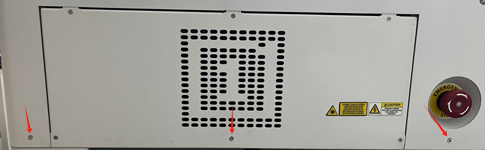
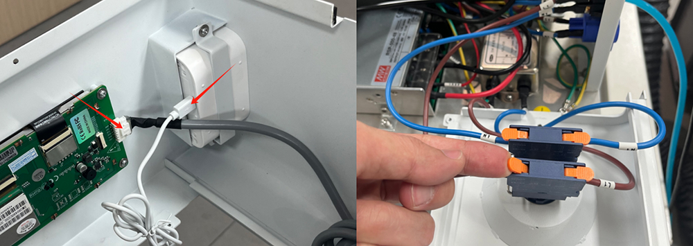
④ Before removing the right-side panel, disconnect the following cables:
- Emergency stop switch power cable
- Touchscreen signal cable
- PM2.5 detector power cable
¶ 2. Removing the TL-time Control Board
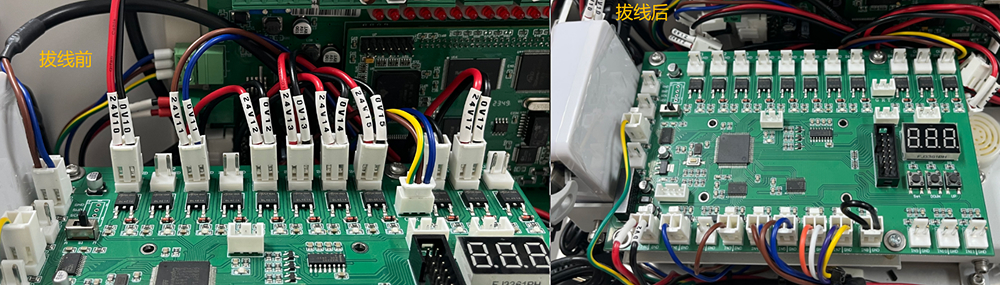
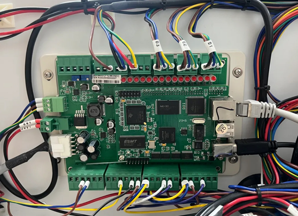
① Disconnect the connectors shown in the image.
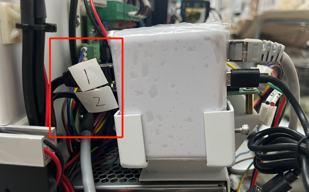
② Remove the two network cables from the switch. Label the cables before removing them as shown in the image.
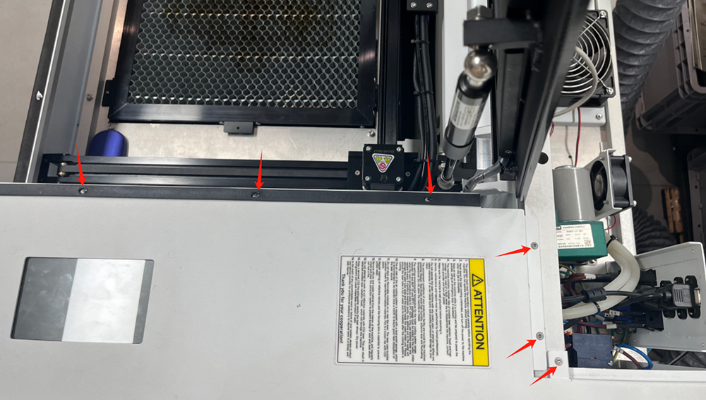
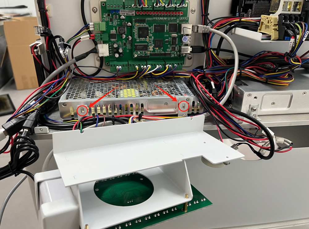
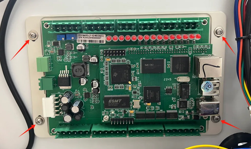
③ Remove the two screws shown in the image. This will allow you to move the TL-time control board aside.
¶ 3. Replacing the Control Board
¶ Removing the Old Control Board
① Disconnect all cables from the control board.
② Use a screwdriver to remove the four screws securing the control board.
¶ Installing the New Control Board
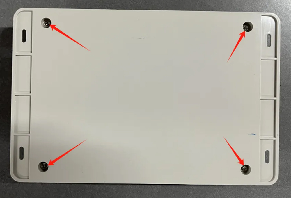
① Remove the outer casing of the control board using a Phillips screwdriver.
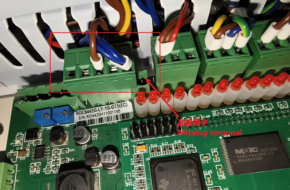
② Secure the new control board to the enclosure and reconnect all cables.
Note: Do not miss any connectors. (The image shows an incorrect connection with a missing terminal.)
¶ 4. Reassembling the Machine
Restore the TL-time control board, switch, and enclosure to their original positions, following the connections made before disassembly.