¶ How to Adjust the Laser Light Path
This guide explains how to adjust the laser light path on the OneLaser X Series safely and correctly. It covers critical precautions, required tools, and preparation steps to help ensure accurate alignment while preventing unnecessary damage or time-consuming recalibration.
¶ Note:
When the device leaves the factory, the optical path has been precisely adjusted to the best state.
If you are not sure whether the optical path of the device has shifted, please do not adjust the optical path lens knob or locking screw at will.
Once the optical path locking screw or knob is adjusted, the optical path of the device may shift.
If it shifts, you may need at least 4 hours to readjust the optical path of the device.
¶ 1. Preparation
¶ ① Material preparation
- Double-sided tape × 1
- 10mm Acrylic × 1
- Flathead screwdriver × 1
- M3 Hexagon wrench × 1
- M2.5 Hexagon wrench × 1
- M2 Hexagon wrench × 1
- One Laser X series × 1
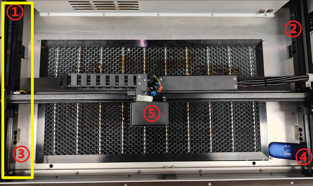
¶ ② Disassembling the Case
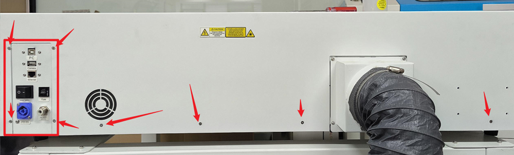
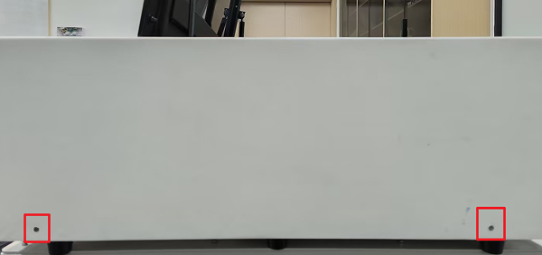
¶ A. Removing the back cover
Use an M2 hexagon wrench and carefully remove the screws according to the instructions in the picture, and place them in a unified manner.
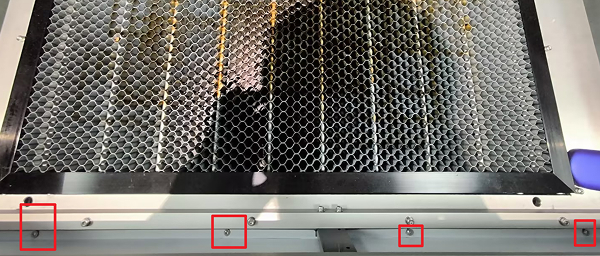
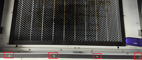
¶ B. Removing the front cover
Use an M2 hexagon wrench and carefully remove the screws according to the instructions in the picture, and place them in a unified manner.
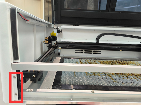
¶ C. Removing the side door
Use an M2 hexagon wrench and carefully remove the screws according to the instructions in the picture, and place them in a unified manner.
¶ ③ Set panel parameters
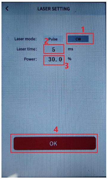
¶ A. Set the burst parameters
a. Click on the menu → Laser setting → Setting parameters
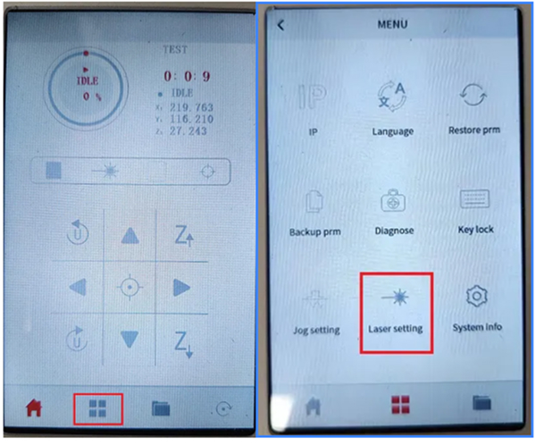
b. Set the burst mode to continuous, the time to 5 ms, and the power to 30%.
¶ 2. Adjustment steps
¶ Note:
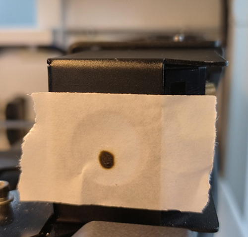
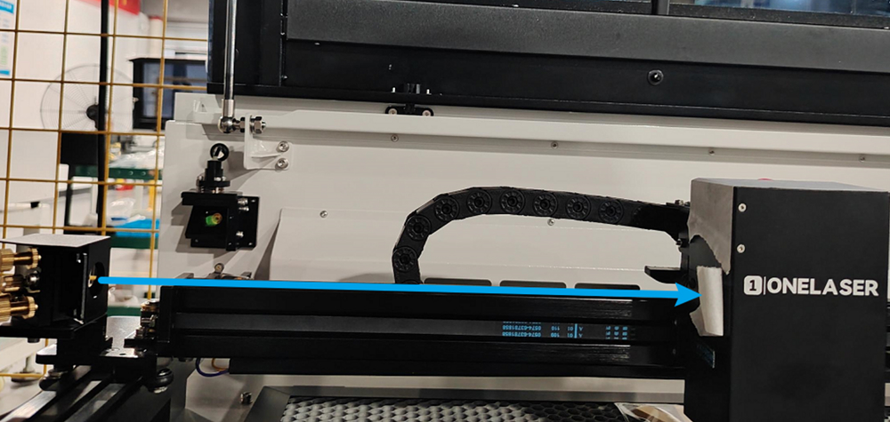
Please stick the double-sided tape on the front of the frame to be adjusted, then move the laser head and lightly press the shot button to adjust the optical path.
During this process, please carefully observe the changes in the optical path.
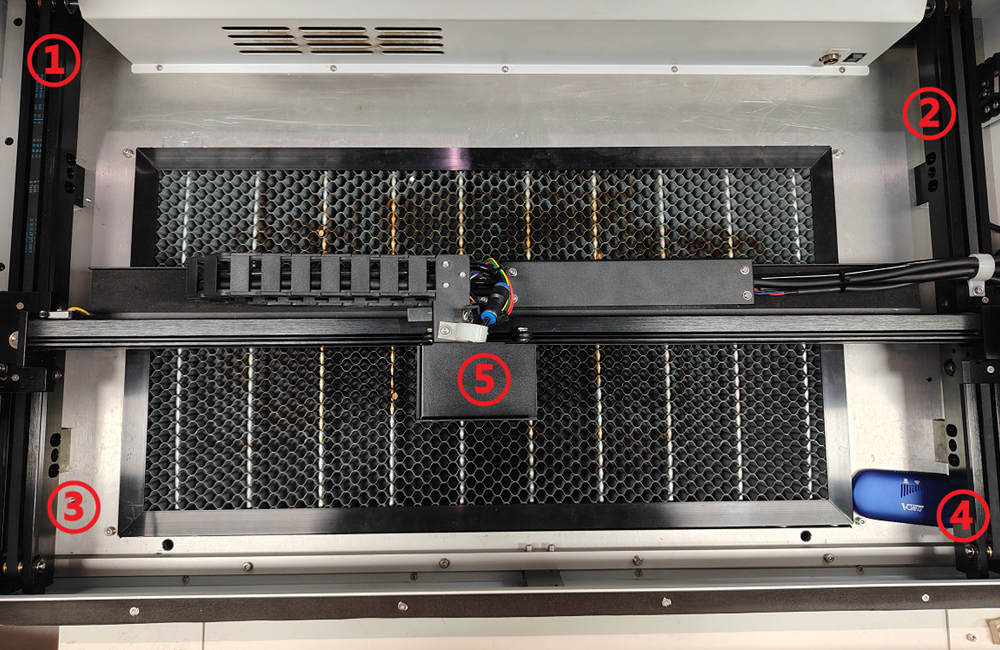
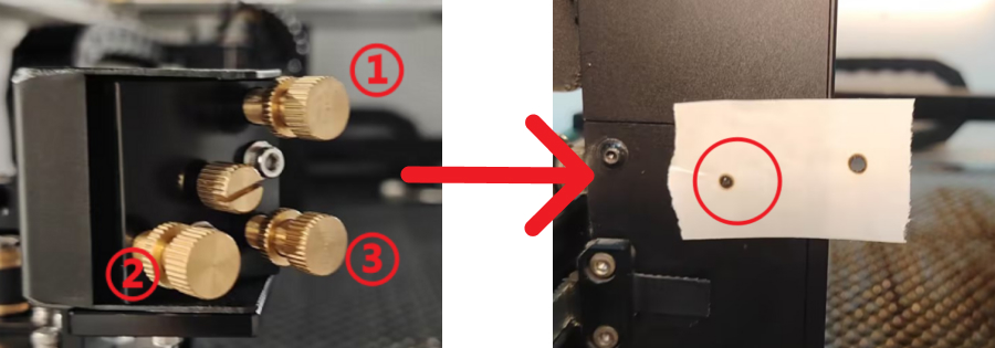
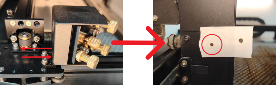
¶ ① Adjust the light path from one reflection to two reflections
Stick the double-sided tape to the front of the second mirror frame.
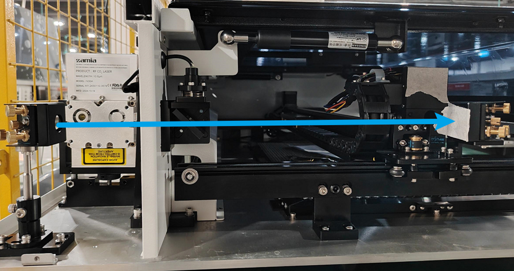
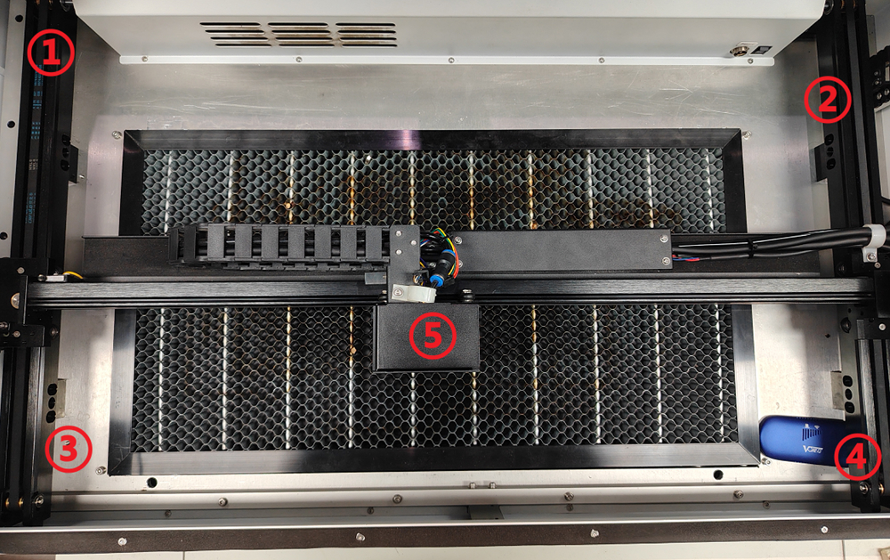
That is, adjust the light source points ① and ③ as shown in the figure below to coincide with each other.
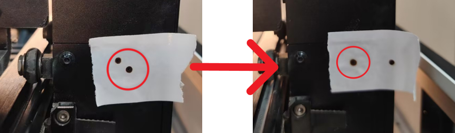
¶ A. Adjust the overlap of ① and ③ light spots
When a large deviation occurs, such as the following:
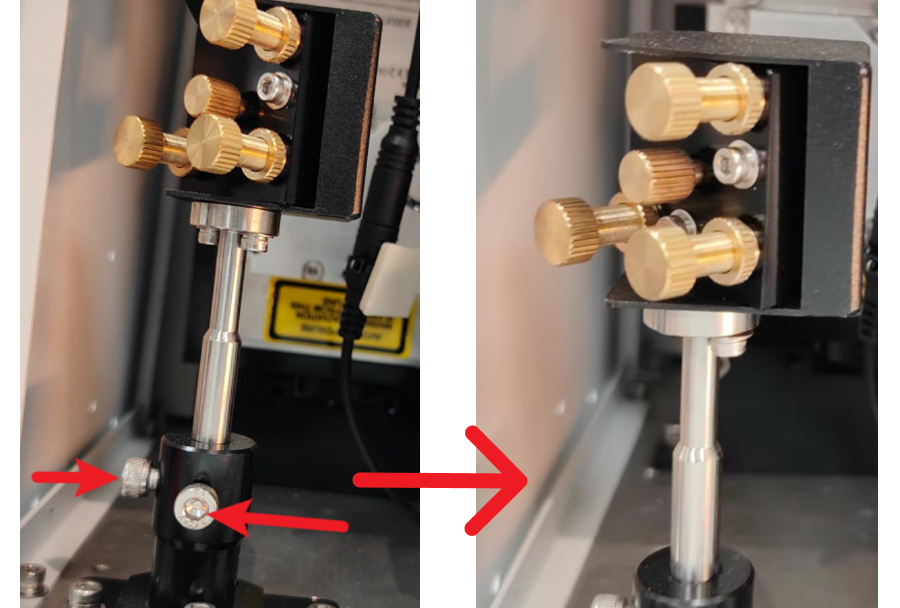
¶ a. Large offset adjustment
At this moment, the light spot is offset to a large extent, and it is necessary to adjust the bottom bracket to make the light spots roughly overlap.
After loosening the fixing screws of the black bracket, start adjusting the upper reflective frame.
During the adjustment process:
- Fix the screws while fine-tuning the frame
- Ensure the light spots roughly overlap
- After tightening the screws on one side, check if there is any deviation
- Observe the direction of movement of the light spot when tightening
- Push the frame in the opposite direction accordingly
- Fix the frame until the lenses roughly overlap
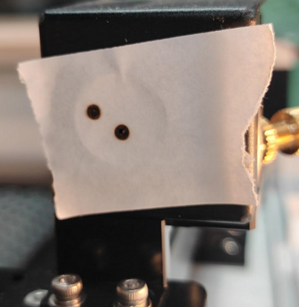
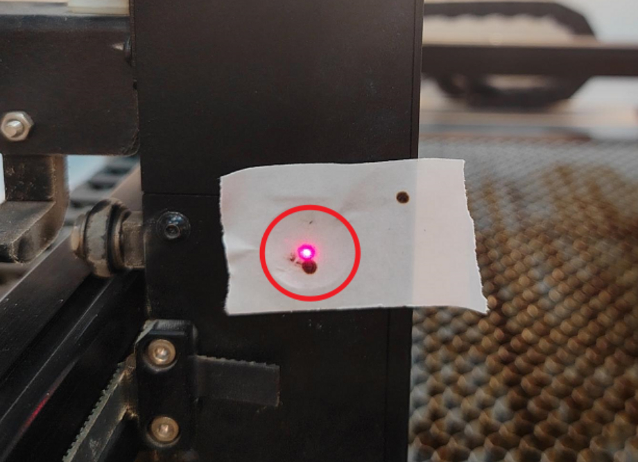
¶ The light spots roughly overlap:
¶ b. Adjust lens distance
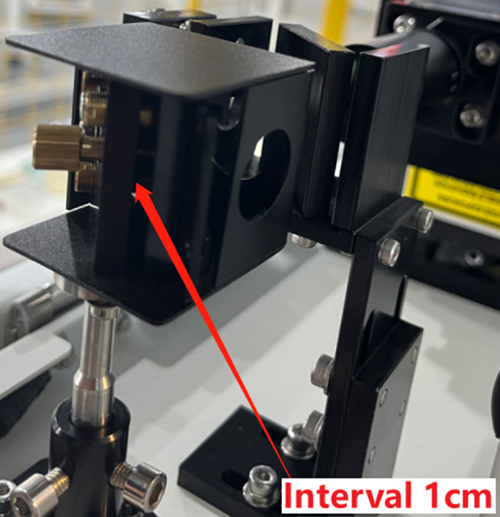
Tighten the three gold nuts on the outside of the lens and the lens will move back, ensuring there is about 1 cm gap between the lens and the frame.
If the distance between the lenses is about 1 cm, there is no need to tighten the nut again.
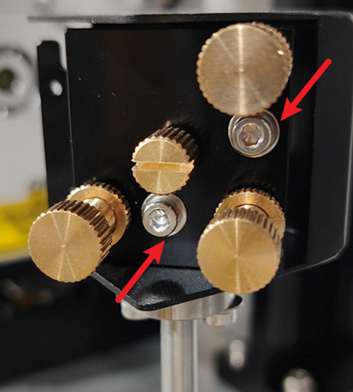
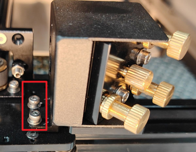
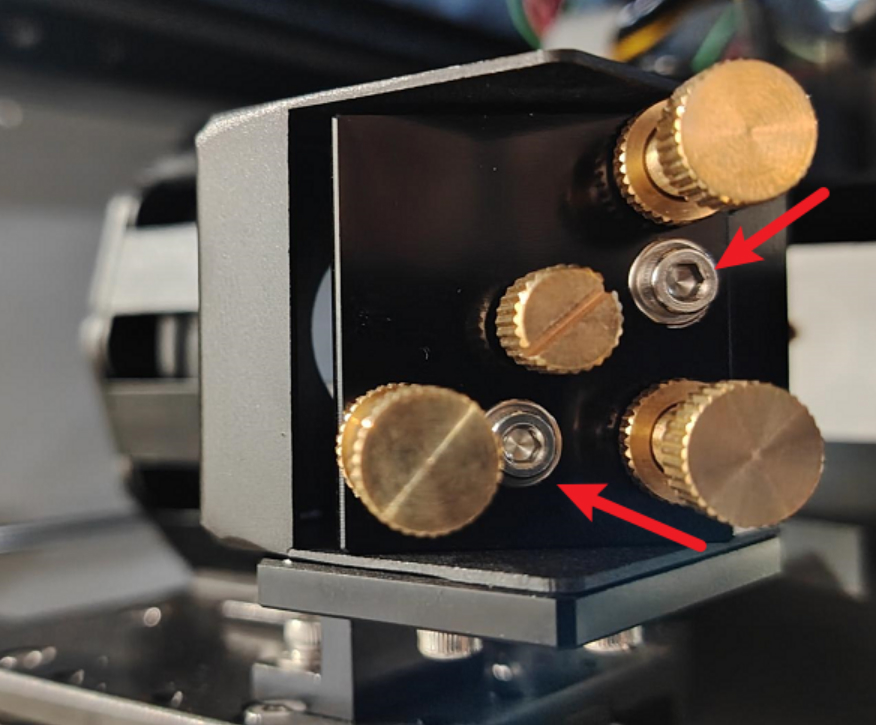
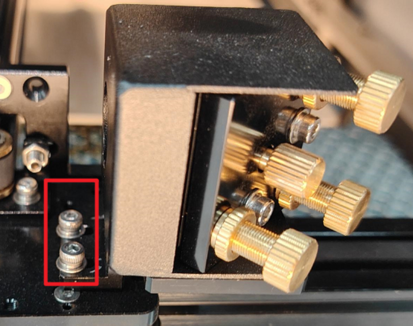
¶ c. Loosen frame nut
Use an M2.5 hexagon wrench to loosen the silver-white nut of the frame.
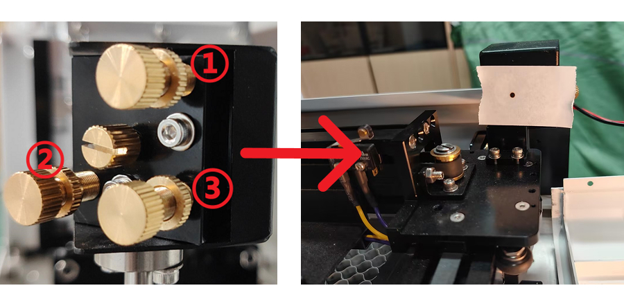
¶ d. Adjustment Instructions
In the figure:
- When screw No. 1 is rotated clockwise, the light source will move downward
- When screw No. 2 is rotated clockwise, the light source will move to the right
- When screw No. 3 is rotated clockwise, the light source will move to the upper left
(Counterclockwise rotation will move the light source in the opposite direction.)
After each fine-tuning of the screw, please slightly tighten the silver-white nut to prevent the light source from shifting a second time.
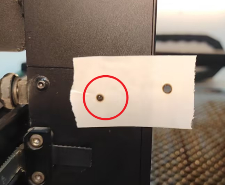
Adjust these three screws until the front and rear light sources coincide at the same point.
¶ 3. Adjust the Optical Path from the Second Reflector to the Third Reflector
Stick double-sided tape to the front of the three-mirror frame.
This step adjusts the light source points ①, ②, ③, and ④ so they overlap and are positioned at the center point.
¶ A. Adjust ① and ② Light Source Points to Basically Coincide
a. Use an M2.5 hexagonal wrench to loosen the two fixing screws of the second mirror frame.
b. Move the frame:
Gently move the second mirror frame, move the laser head back and forth, and press the point shooting button to let the laser hit light source points ① and ②.
After the front and rear light spots appear on the third mirror frame, fix one screw and gently swing the second mirror frame to make light source points ① and ② basically overlap.
After overlap, tighten the screw.
¶ B. Adjust the Overlap of Light Source Points ①, ②, ③, and ④
a. Use an M2.5 hexagonal wrench to loosen the two silver nuts on the frame.
b. Adjustment Instructions:
- When screw No. 1 rotates clockwise, the light source moves downward
- When screw No. 2 rotates clockwise, the light source moves to the right
- When screw No. 3 rotates clockwise, the light source moves to the upper left
- Counterclockwise rotation moves the light source in the opposite direction
After each fine-tuning of the screw, slightly tighten the silver-white nut to prevent the light source from shifting again.
Adjust these three screws until ①, ②, ③, and ④ light sources overlap.
¶ C. Adjust ①, ②, ③, ④ Light Source Points to the Center Point
a. When there is a left-right deviation from the center point, adjust it by adjusting the two-mirror frame
Use an M2.5 hexagonal wrench to loosen the two silver nuts.
Gently push the second mirror frame:
- If biased to the left, move it to the right
- If biased to the right, move it to the left
- Adjust until the light source is centered.
b. Height deviation adjustment
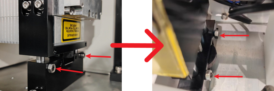
When there is a height deviation from the center point, the laser height needs to be adjusted.
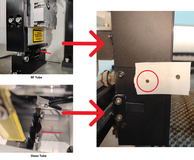
i. Use an M2.5 hexagonal wrench to loosen the two jacking bolts on the laser base.
RF Tube:
Turn the knob clockwise to raise the laser tube, counterclockwise to lower it.
Glass Tube:
Adjust in the same way and tighten the bottom jacking bolt after adjustment.
Note:
The front and rear heights of the laser must remain consistent, and the top screws on both sides must be tightened.
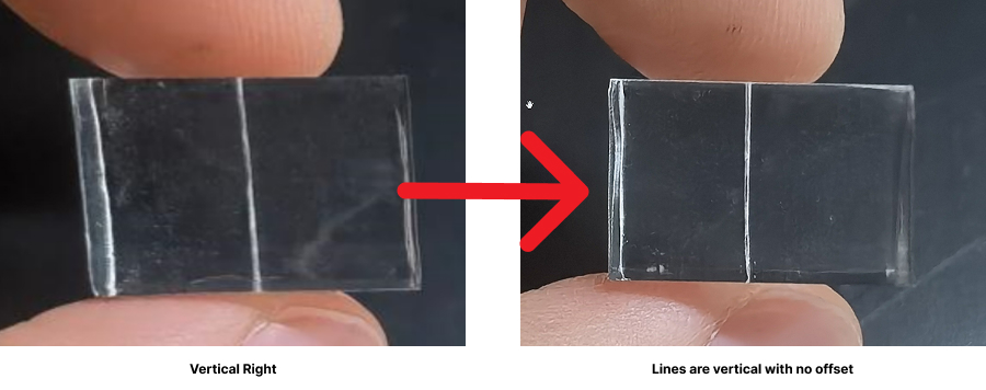
¶ D. Adjust Verticality
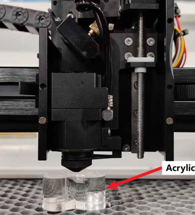
Set the burst power to 60% and burst through 10 × 10 mm acrylic.
Visually check whether the cutting result is vertical.
If the verticality leans to the left, raise the laser
If the verticality leans to the right, lower the laser
¶ 4. Next Steps
After completing the adjustment:
- Ensure all fixing screws are fully tightened
- Reinstall all door covers
- Tighten all screws securely