¶ Beam Path Misalignment (RF Tube) - Hydra Series
¶ Problem Description
- Regardless of the position on the workbed, the processing results in the far areas (further away from the origin) are consistently worse than those in the near areas. This manifests as the kerf widening, the cut becoming gradually shallower, or the laser failing to cut through the material entirely.
- When checking beam alignment by moving the laser head to the four corners of the workbed, the burn marks left on the tape do not coincide.
¶ Cause
Beam path misalignment can be caused by many factors, including:
- The angle of a mirror mount was accidentally shifted during the cleaning of the mirrors.
- Shipping and vibration caused the optics to shift out of alignment.
¶ Solution
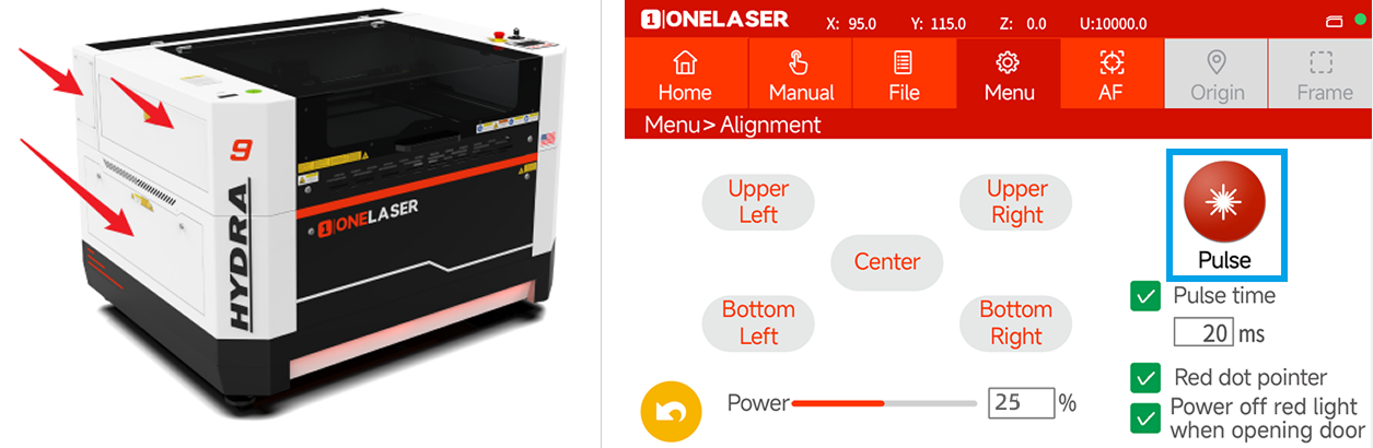
1.Remove Access Panels: Detach the three panels on the left side of the Hydra unit (as illustrated) to provide access for viewing and adjusting the beam path.
2.System Preparation:
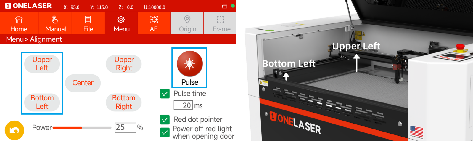
- Navigate to the "Alignment" interface on the Hydra touchscreen.
- Set the laser power to approximately 25%.
WARNING: The "Pulse" button will be used to emit laser light for beam location verification. When activating "Pulse", ensure NO part of the human body is in, or can cross, the beam path.
3.Beam Path and Mirror Identification: The laser beam path and the corresponding mirror assemblies are identified in the figure below:
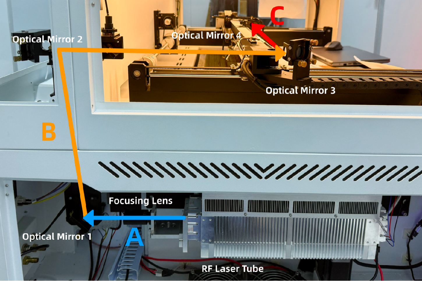
¶ Method 1. Adjusting Optical Path A
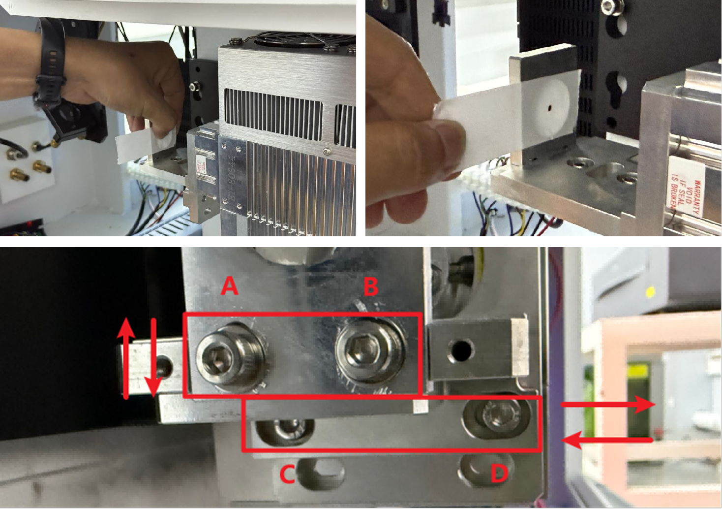
1.Remove the focusing lens and place a piece of double-sided tape on the base. Press “Pulse” and check the burn mark.
- If the mark is off-center, adjust screws A/B (vertical) or C/D (horizontal) using a 3 mm hex wrench.
- Repeat until the burn mark is centered.
2.Reinstall the focusing lens and place tape at Optical Mirror 1. Pulse again and adjust if needed.
Important: Press two adhesive sides of tape together first to avoid contaminating the lens.

¶ Method 2. Adjusting Optical Paths B & C
 |
Important: In Optical Path C, Optical Mirror 3 and Optical Mirror 4 are shared by the 70W RF tube and the glass tube and should not be adjusted. Adjust only Optical Mirror 1 and Optical Mirror 2. |
¶ Optical Mirror 1 & Optical Mirror 2 (Fine-Adjustment Method)
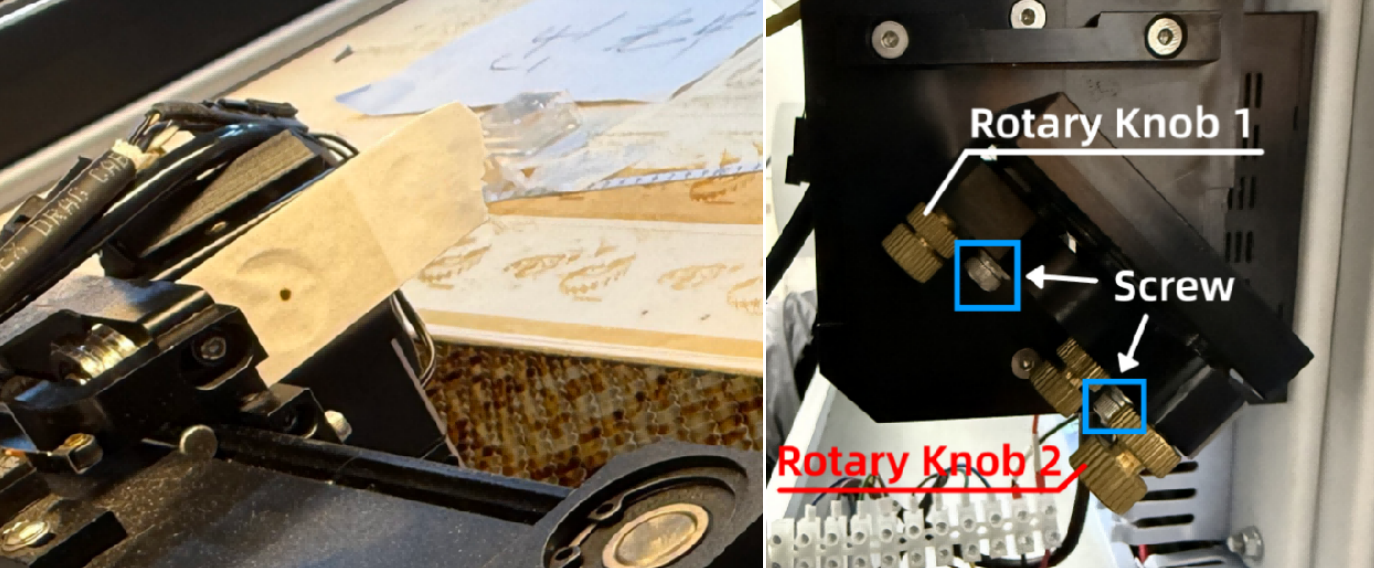
1. Apply tape over the through-hole on Optical Mirror 2. Pulse and adjust via Optical Mirror 1 knobs.
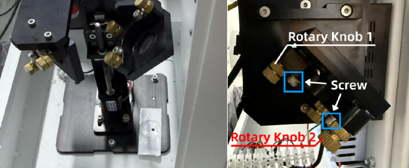
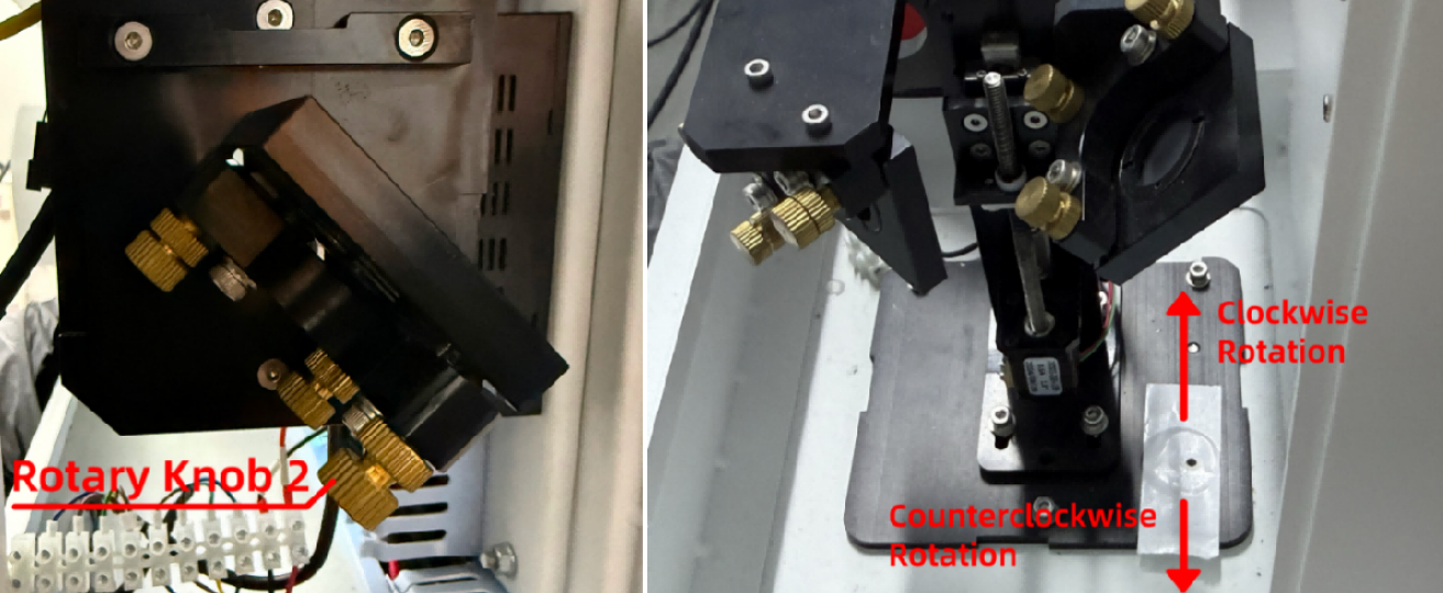
Optical Mirror 1 Knob Guide
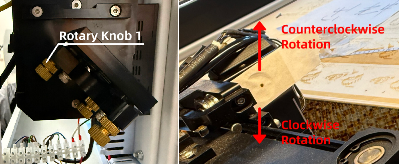
Rotary Knob 1:
- Clockwise → shifts burn mark right
- Counterclockwise → shifts burn mark left
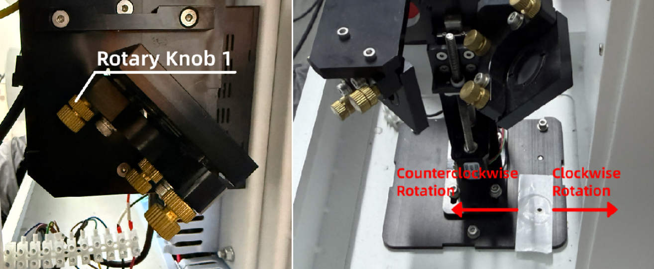
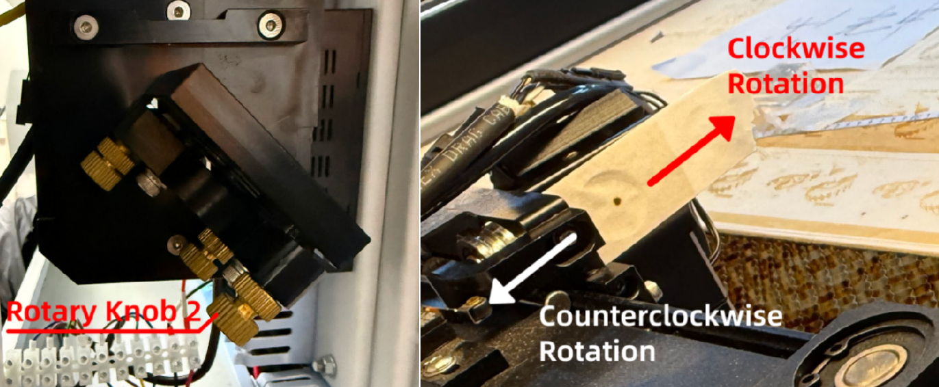
Rotary Knob 2:
- Clockwise → shifts burn mark inward
- Counterclockwise → shifts burn mark outward
2. Apply tape to Optical Mirror 3 and the red-light port. Adjust Optical Mirror 2 knobs until the burn mark is centered.

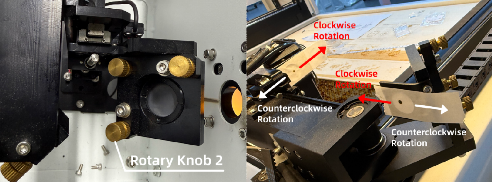
Optical Mirror 2 Knob Guide
Rotary Knob 1:
- Clockwise → shifts burn mark down
- Counterclockwise → shifts burn mark up
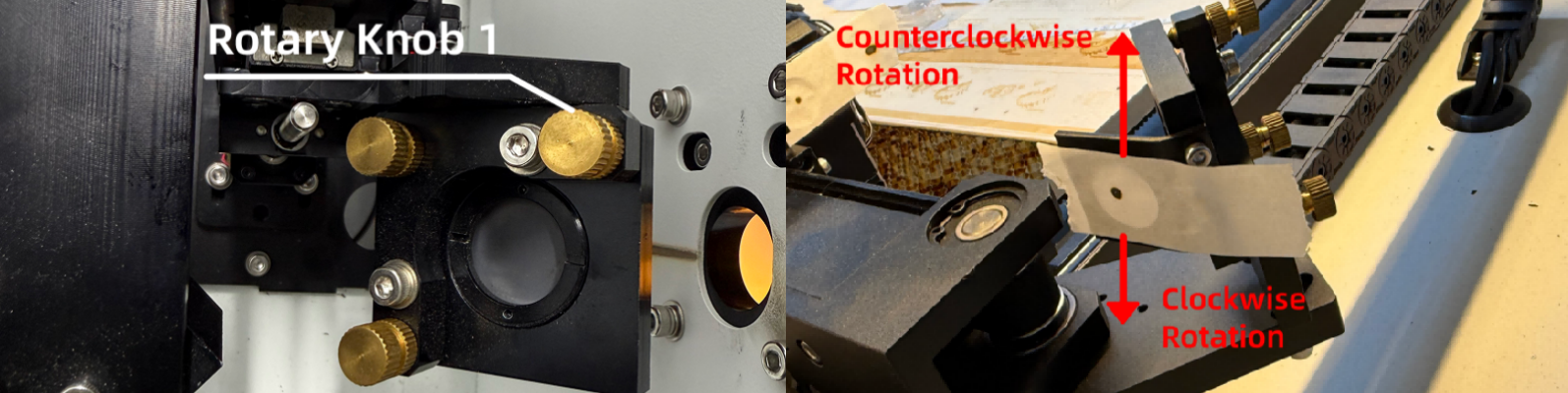
Rotary Knob 2:
- Clockwise → burn mark moves left
- Counterclockwise → burn mark moves right
3. Apply tape on Optical Mirror 4. Move the laser head to upper-left and bottom-left. The marks must overlap.
¶ Adjusting Only Optical Mirror 1 (Simplified Method)
1. Apply tape on Optical Mirror 4. Pulse and adjust Optical Mirror 1 knobs until centered.
Optical Mirror 1 Knob Guide
Rotary Knob 1:
- Clockwise → burn mark moves up
- Counterclockwise → burn mark moves down
Rotary Knob 2:
- Clockwise → burn mark moves right
- Counterclockwise → burn mark moves left
2. Apply new tape on Optical Mirror 4. Move to upper-left and bottom-left corners. Verify marks overlap.
Important Reminder:
If these steps do not resolve the issue, please submit a support ticket on ZOHO: https://zohodesk.1laser.com/portal/en/newticket. A technician will then be able to conduct a more in-depth diagnosis and resolve your problem.