¶ Hydra Series Manual - Operation Section
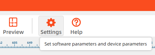
¶ 4.1 Machine View
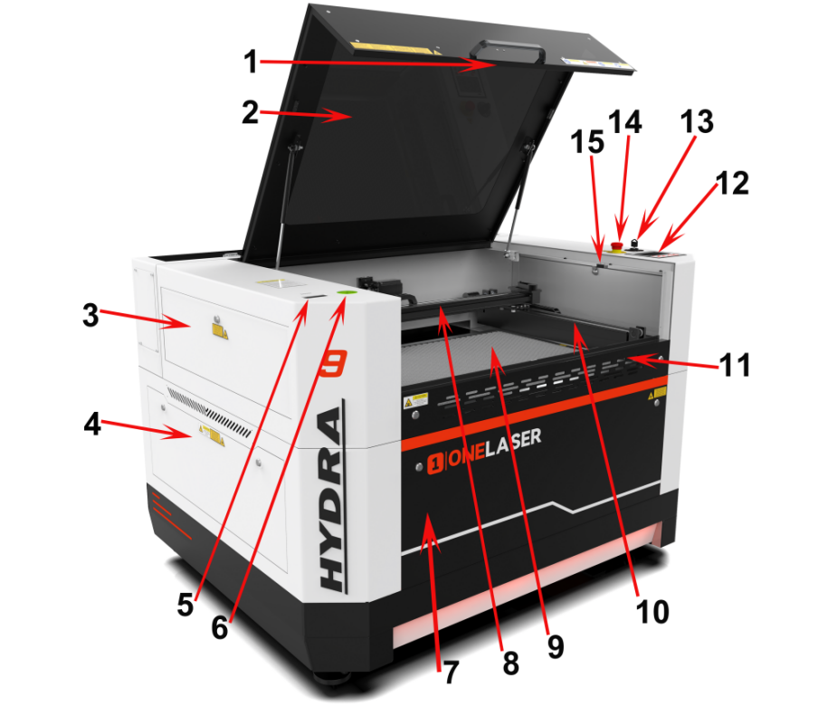
1. Camera
Camera function.
2. Top flap
If the Top flap is opened, no data is processed. When the protection cover is opened during working, the motion system is stopped and the laser source is turned off. During processing of commands the protection cover must only be opened after pressing the “Pause “button.
3. Left-up side door
Many parts inside it, such as Y axis rail.
4. Left side door
Many parts inside it, such as RF tube.
5. Air quality detector
Detects air temperature and humidity as well as PM2.5.
6. Green Universal Spirit Level
Detect and adjust the horizontal or vertical position to ensure the machine is accurately leveled.
7. Front door
To clean the waste after working or remove the honey comb table.
8. X axis (left and right movement)
The motion system is that performs the mechanical movements in X direction.
9. Honey comb table
The honey comb plate sits on top of the blade bed and has indexing pins for alignment.
10. Y axis (forward and backward movement)
The motion system is that performs the mechanical movements in Y direction.
11. Front up door
Open this door to use pass-through door.
12. Control panel
You can control the X-axis, Y-axis and Z-axis manually by the display panel, it also shows the working time, power, speed and the whole working time and affords many function options.
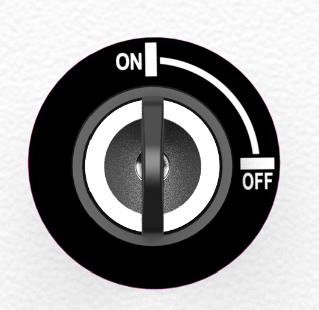
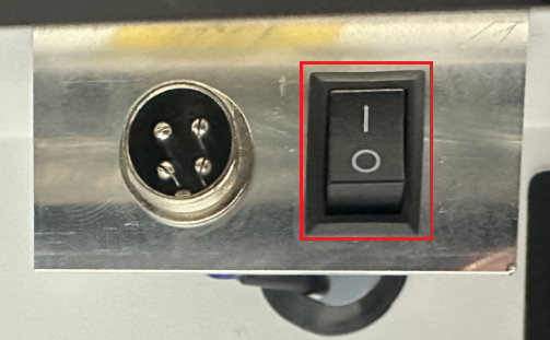
13. Key switch
To turn on the machine.
14. Emergency stop switch
Once there’s an accident happen (laser catch fire, laser out leakage) during working, please turn off this switch immediately. It will be cut off the laser power and motion power immediately.
15. Door protection sensor
Laser will stop working once the cover is opened during working.
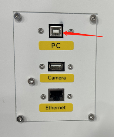
16. Ethernet connector
Connect machine with Ethernet cable.
17. Camera connector
Connect the camera.
18. PC connection port
Connect machine with PC cable.
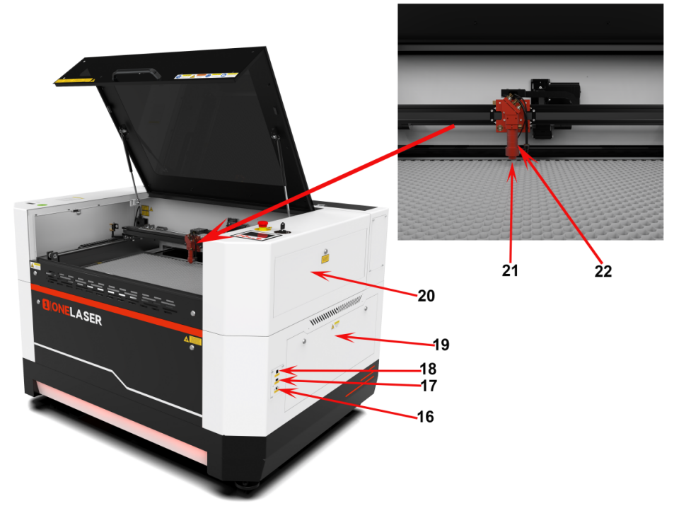
19. Right side door
Many parts inside it, such as Relay,AC contactor.
20. Right-up side door
Many parts inside it, such as Y axis rail.
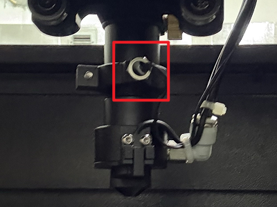
21. Auto-focus sensor
Used for the automatic focusing of the table.
22. Laser head
Laser beam and red dot pointer are all come out from the laser head.
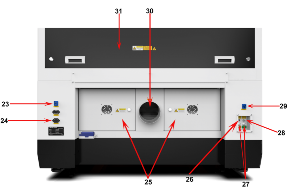
23. Power socket
Connect the power cable.
24. Serial plate
Check the serial info.
25. Rear cover
Many parts inside it, such as 48V power supply.
26. “No-Water protection” signal port
This port is connecting the chiller with the signal cable.
27. Water in and water out
Connect to the water pipes.
28. Air intake
Connect the air pipe.
29. Chiller power socket
To connect the chiller power.
30. Exhaust hose
Connect the exhaust hose.
31. Laser tube cover
Many parts inside it, such as laser tube.
¶ 4.2 ON/OFF Switch
Safety Conditions MUST Be Confirmed Before Startup:
1.Clear all materials and foreign objects from the worktable to prevent collision damage during laser head homing.
2.Ensure the top access door is securely closed.
3.Verify normal operation indicators for auxiliary systems (exhaust/cooling).
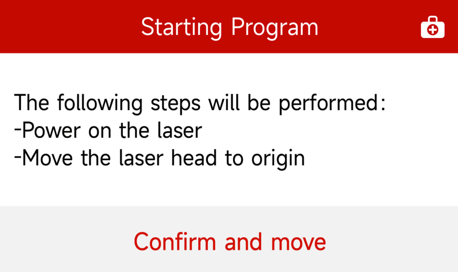
Rotate the safety key switch to the ON position. Then press "Confirm and Move" on the touchscreen control panel. The system will initiate the homing procedure. Upon completion, the home screen will display indicating the system is ready for operation.
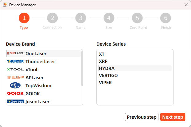
¶ 4.3 Make Connection Between PC and Machine
¶ 4.3.1 Software installation
MakerBoost
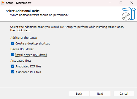
During installation, check the box for "Install device USB driver". Wait for the driver to download automatically. Finally, click "Finish" to complete the installation.
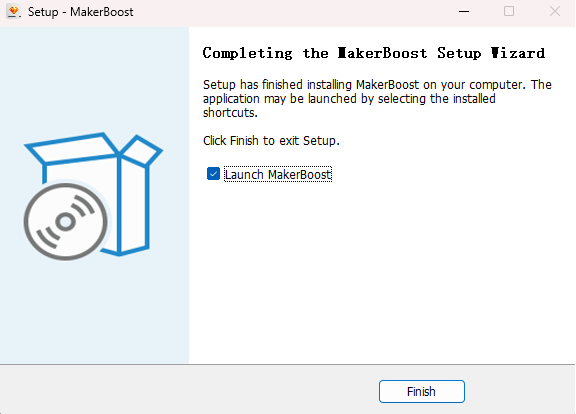
The "MakerBoost" desktop icon will be created automatically. The software is now ready for use.
Lightburn
Please download the corresponding Lightburn at the link below:
https://lightburnsoftware.com/pages/download-trial
If you use USB cable connection, please install the USB driver.
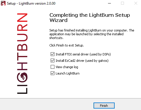
After selecting your options, click "Finish" and then wait for the driver download to complete. You can confirm this and then end the installation process.
A "Lightburn" icon will be automatically added to your Desktop, you are now ready to use the Lightburn.
¶ 4.3.2 Wired Connection
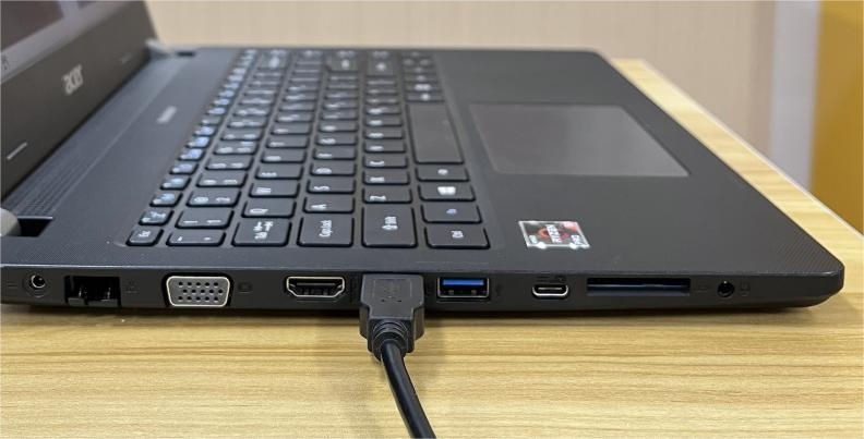
USB Cable Connection
Connecting the Computer and the machine by using the USB cable (Please use a docking station or adapter to connect for MacOS). Like below:
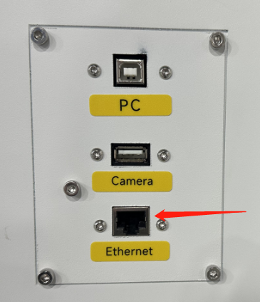
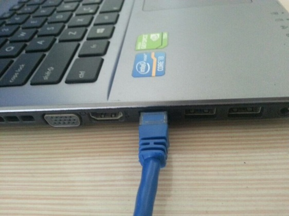
Ethernet Cable Connection
Connecting the Computer and the machine by using the Ethernet cable (Please use a docking station or adapter to connect for MacOS). Like below:
To establish communication between the PC and machine via the above methods, follow these steps:
MakerBoost
Make sure that you have your PC connected to the machine via USB cable or Ethernet cable.
Click "Switch" from right bottom corner of the software, then click "Find" to set up by the Devices setting.
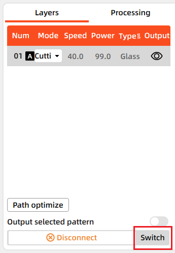
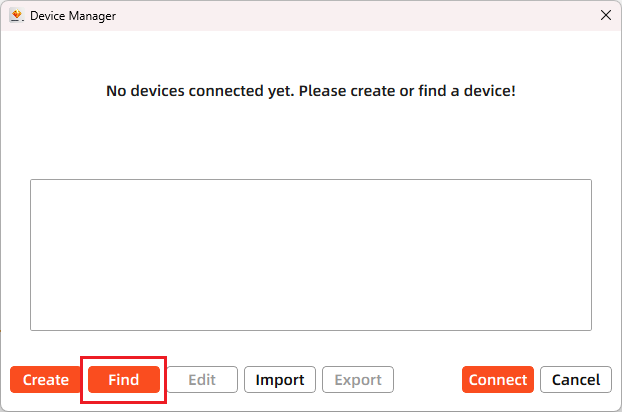
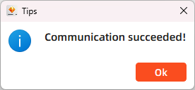
Then follow instructions to complete the connection steps step by step. Select the connection you just created and the display shows "Communication Succeeded" to indicate a successful connection. Now MakerBoost communicates with your laser machine via USB cable or Ethernet cable.
Lightburn
Make sure that you have your PC connected to the machine via USB cable or Ethernet cable.
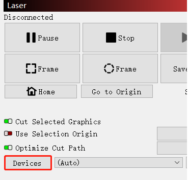
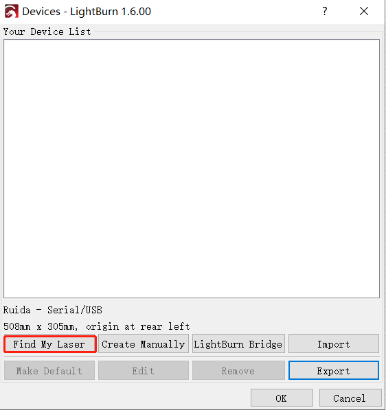
Click "Devices" from right bottom corner of the software. Click "Find My Laser" to set up by the Devices setting.
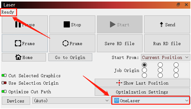
Then follow instructions to complete the connection steps step by step. Select the connection you just created and the display shows "Ready" to indicate a successful connection. Now Lightburn communicates with your laser machine via USB cable or Ethernet cable.

When connecting the machine and the PC for the first time, it may take a few minutes for the operating system to recognize the machine and install the driver.
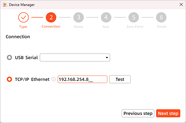
¶ 4.3.3 Remote Connection
¶ Network Cable Connection
Connect both the Hydra and computer to the network using Ethernet cables.
Critical: Ensure they reside on the same subnet (e.g., 192.168.1. XXX).
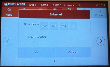
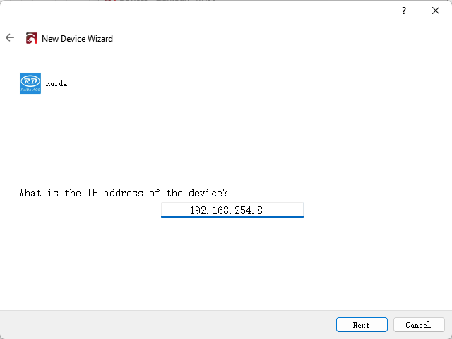
- How to Viewing/Modifying Hydra IP Address?
To establish communication between the PC and machine via the above methods, follow these steps:
MakerBoost
Click "Switch" from right bottom corner of the software, then click "Create" to set up by the Devices setting.
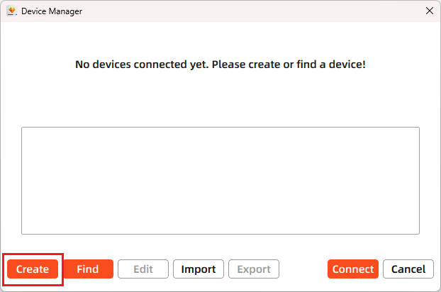
Then follow instructions to complete the connection steps step by step. Critical: The entered IP MUST exactly match the Hydra's configured address.
After successful device creation, select the newly created "Hydra 70" entry in the machine list. Then click the "Connect" button. The software will instantly activate the connection.
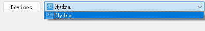
Lightburn
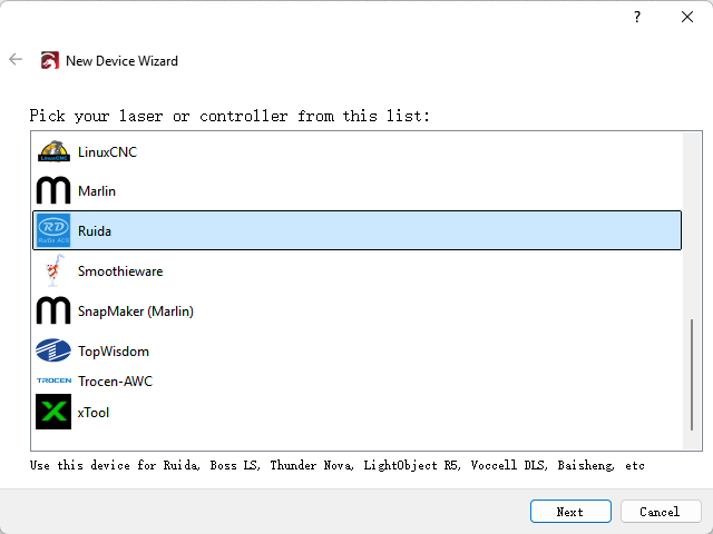
Click "Devices" from right bottom corner of the software. Click "Create Manually" to set up by the Devices setting.
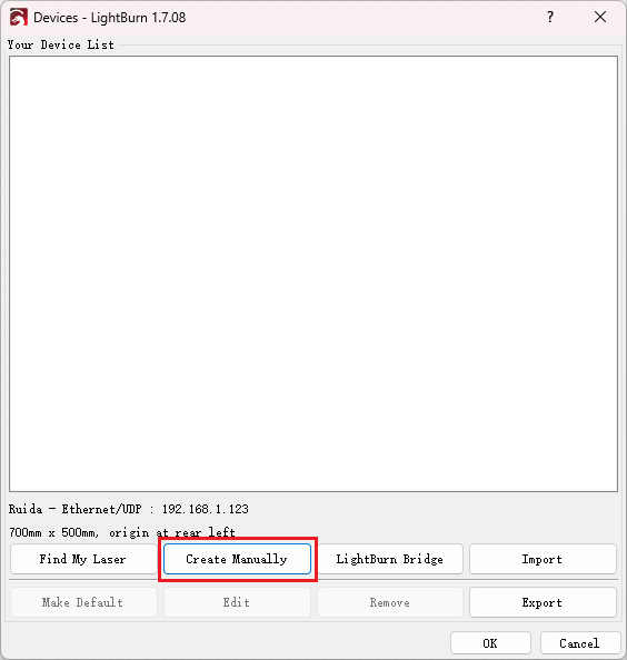
Then follow instructions to complete the connection steps step by step. Critical: Under Controller Type dropdown, MUST select "Ruida". The entered IP MUST exactly match the Hydra 70's configured address.
After successful device creation, locate and select the newly created "Hydra" entry in the bottom-right panel (Device List section).
¶ WIFI Connection
The system supports two WiFi modes: Hotspot Mode and Repeater Mode.
1.Hotspot Mode
Connect your computer directly to the Hydra 70's built-in router:
- SSID Format: [Machine Model]_Hotspot_[Last 5 digits of S/N]
(Example: HYDRA70_Hotspot_8A2B4)
- Default Password: 12345678
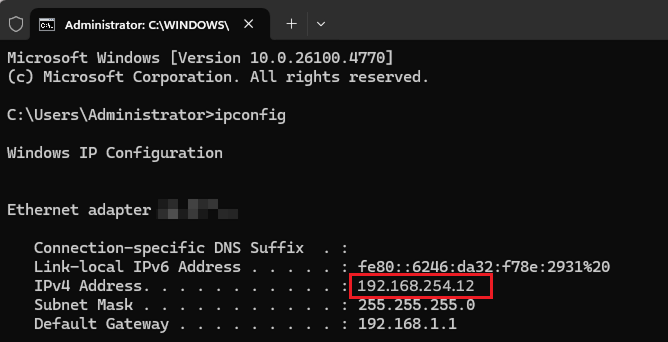
The hotspot's default IP subnet is 192.168.254.xxx. Set Hydra 70's IP address within 192.168.254.xxx. Important: The last octet of the hotspot's IP must differ from Hydra 70's IP address.
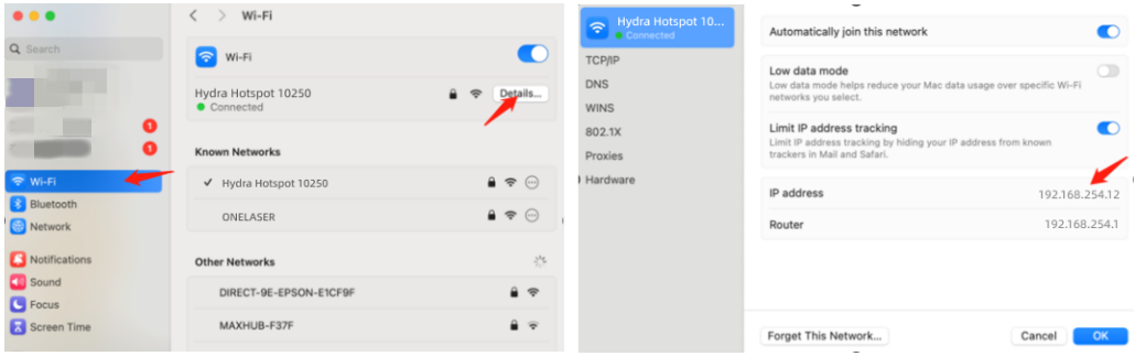
To verify the hotspot subnet on your computer:
①Windows: Open Command Prompt, type "ipconfig", and check the IPv4 address.
②Open WiFi settings, view network details, and locate "IP address".
- How to Modifying Hydra IP Address?
2.Repeater Mode
Users can bridge the Hydra's WiFi module to their primary router network. This allows both the Hydra and computer to connect remotely via the user's regular WiFi.
Setup Procedure:
1.Connect your computer to the Hydra's hotspot:
- SSID: [Machine Model]_Hotspot_[Last 5 S/N digits]
- Password: 12345678
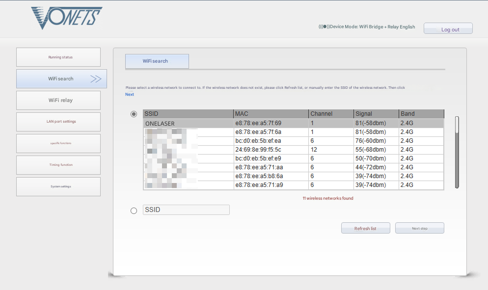
2.Open a web browser and enter: 192.168.254.254 or http://vonets.cfg


3.Log in to the bridge device console:
- Username: admin
- Password: admin
- Click "Login"
4.Configure bridging:
- Click "WIFI Search"
- Select your target WiFi network
- Click "Next"
5.Enter the target WiFi's password. Check and disable hotspot. Do not modify advanced/other settings.
6.Click "Submit".

The device supports Wi-Fi 4 (802.11n) / Wi-Fi 5 (802.11ac) protocols. When bridging, the upstream router must not exceed Wi-Fi 5 standards (i.e., cannot use Wi-Fi 6/6E or Wi-Fi 7).
To establish communication between the PC and machine via the above methods, follow these steps:
MakerBoost
Click "Switch" from right bottom corner of the software, then click "Create" to set up by the Devices setting.
Then follow instructions to complete the connection steps step by step. Critical: The entered IP MUST exactly match the Hydra 70's configured address.
After successful device creation, select the newly created "Hydra 70" entry in the machine list. Then click the "Connect" button. The software will instantly activate the connection.
For the detailed user manual of MakerBoost software, contact ONELASER Support to obtain the documentation.
Lightburn
Click "Devices" from right bottom corner of the software. Click "Create Manually" to set up by the Devices setting.
Then follow instructions to complete the connection steps step by step. Critical: Under Controller Type dropdown, MUST select "Ruida". The entered IP MUST exactly match the Hydra 70's configured address.
After successful device creation, locate and select the newly created "Hydra 70" entry in the bottom-right panel (Device List section).
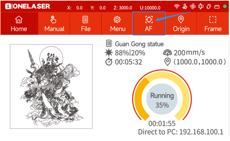
¶ 4.4 How to use the display
The Hydra features our self-developed GT5 control system – currently the most advanced on the market – combined with a touchscreen + physical keys dual-control panel, delivering smooth and intuitive operation.
|
Controller Model |
RDC6442G |
|
Memory |
1 GB |
|
USB Drive Compatibility |
Supports all storage capacities and models |
|
Software Capabilities |
Power-loss recovery / Parameter backup logic / Job time calculation / Online motherboard upgrades |
|
Display Features |
Real-time adjustment of power/speed / Thumbnail previews for graphics / Live progress tracking during processing |
Physical buttons and connector
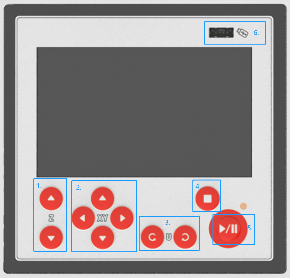
1. Z axis button: control the table to move in Z-axis.
2. Direction button: control the laser head to move in X and Y axis.
3. Spare button
4. Esc button: exit the current state.
5. Pause/Start button: pause/start the current job
6. U-disk port: for connecting U-disk
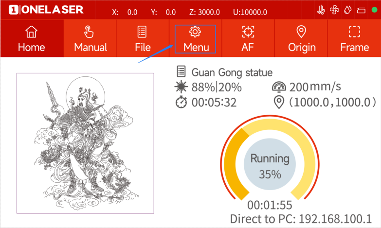
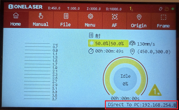
Home page
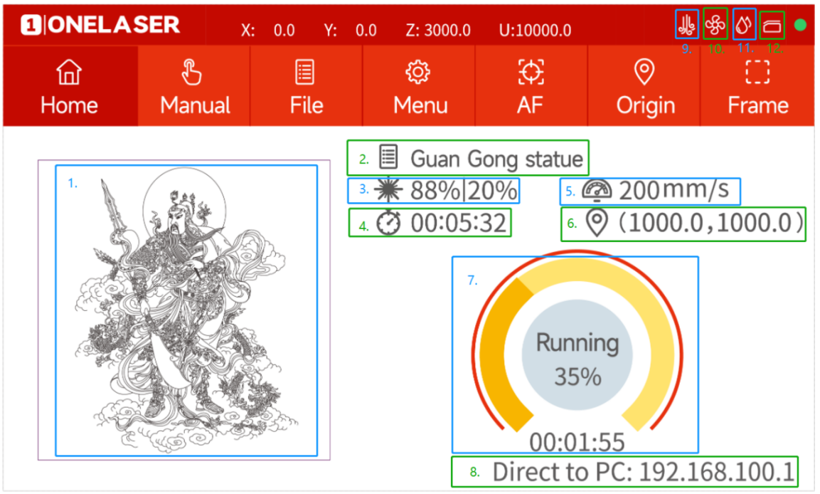
1. Preview image: preview effect of the current file.
2. Name: The name of the file.
3. Power setting: Max power and min power.
4. Working time: The running time of this job.
5. Speed setting: Running speed of your job.
6. Coordinates: The coordinate of origin you set.
7. Processing progress: Check the processing status of the job.
8. IP address: Show the IP address of machine.
9. Air assist: It will be displayed when the machine is in standard mode. Intelligent mode as default settings.
10. Exhaust: It will be displayed when the machine is in standard mode.
11. Water protection: Only for DC tubes.
12. Door protection status: All doors are closed when it’s gray. It’s red when a door is opened.
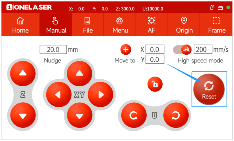
Manual page
This screen will show the manual buttons and the functions for adjusting the speed of the axes.
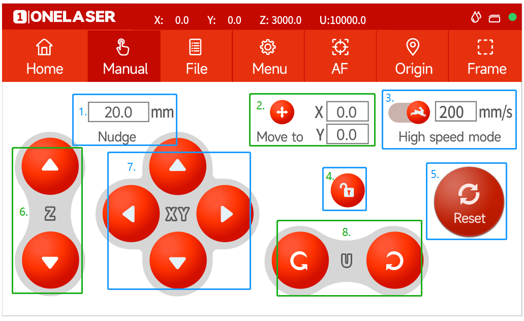
1. Nudge: Set the travel distance when moving each axis manually.
2. Target position: Set a coordinate, then the laser head will move to here.
3. Mobile mode: Change the mode.
4. Lock button: Lock or unlock the manual buttons.
5. Reset button: To reset X/Y axes.
6. Z axis button: control the table to move in Z-axis
7. Direction button: control the laser head to move in X and Y axis.
8. Spare button
File page
This screen will display the file details, where you can select the corresponding file and modify the speed or power parameters of the file.
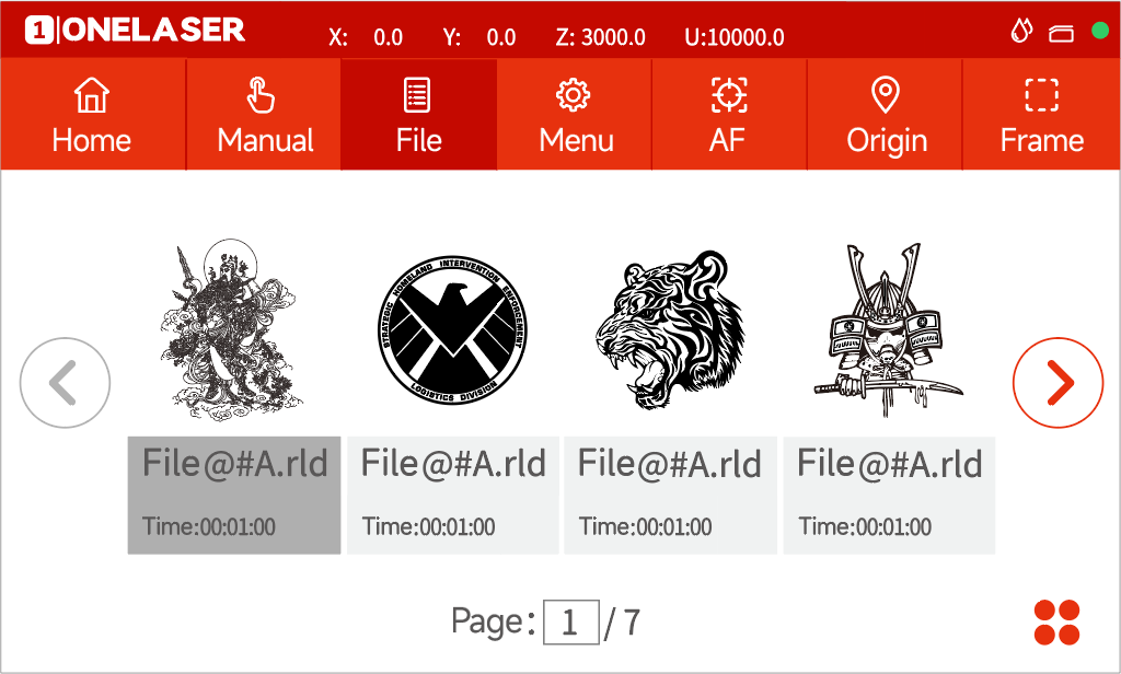

Settings: check more settings of file.
Select and hold a file for 2 seconds to select it to run.
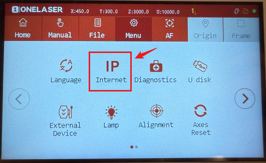
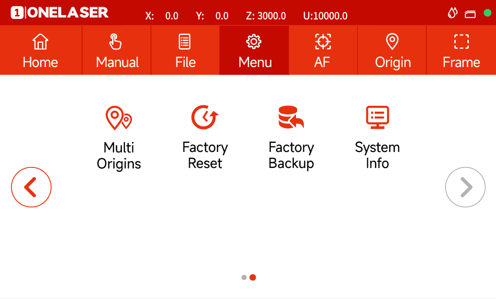
Menu page
This interface will show more features such as language, Internet and so on.
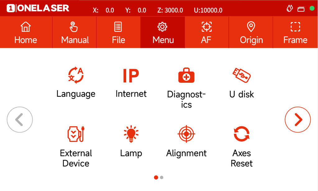
1. Language: Change the language of panel.
2. Internet: Set the IP address.
3. Diagnostics: the “Diagnostics” interface shows some system input information, such as limiter status, and the status of the door protection etc.
4. U disk: Upload files via U-disk.
5. External Device: Switch the intelligent and standard mode. And set delay time for exhaust and air assist time.
6. Lamp: Adjust the brightness of led lamp.
7. Alignment: Check and adjust the laser beam.
8. Axes Reset: Reset all axes.
9. Multi Origins: Set multi origins.
10. Factory Reset: Reset the vendor settings.
11. Factory Backup: Set the current setting as vendor settings.
12. System Info: Check all info of your laser.
Others

Auto focus button: Click this button to auto focus after placing the materials on working area.

Origin button: Click this button after selecting a file.

Frame button: Click it to run a frame of your file after setting an origin.
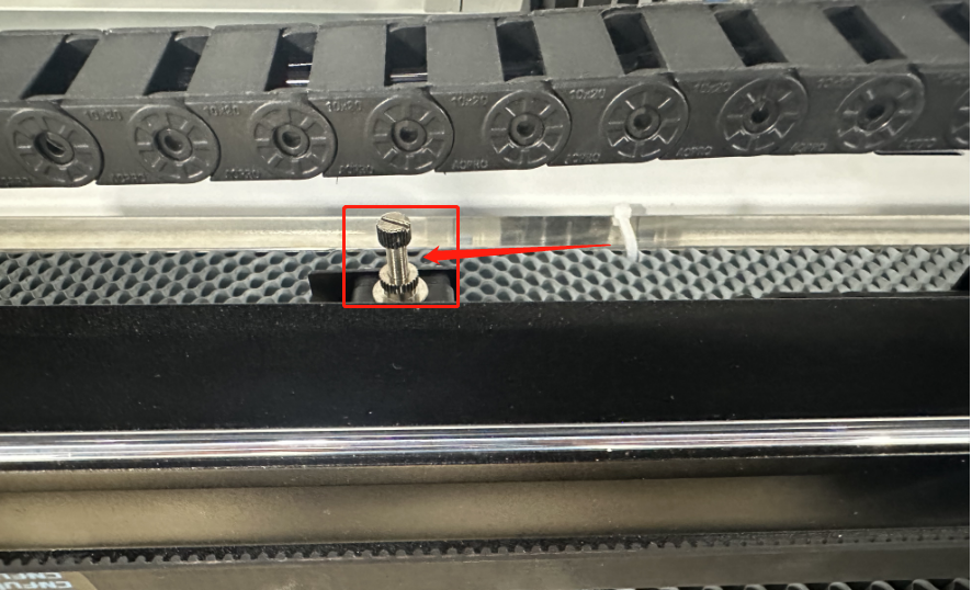
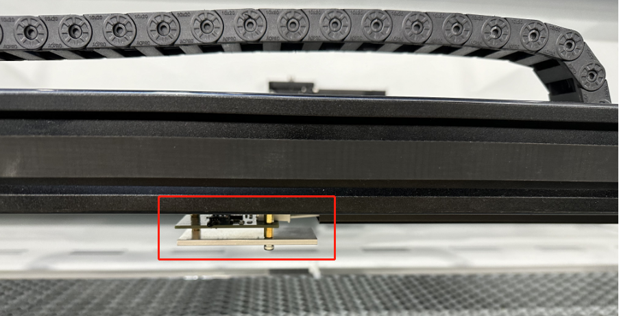
¶ 4.5 How to use the manual or auto focus function
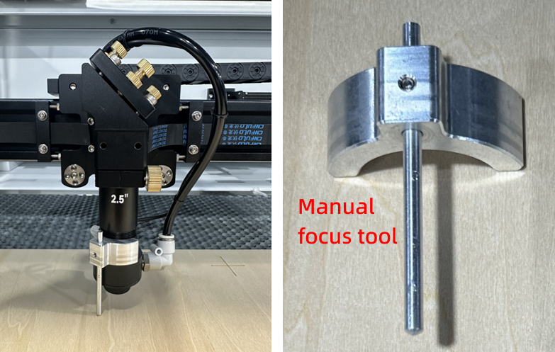
1) How to Use the Manual Focus Function
Place the manual focus tool between the material and the laser head.
The focus distance is 6mm.
2) How to Use Auto-focus Function
Auto focus function can move up and down the laser head to make sure the most proper distance between the material and the focal lens.By using the auto focus function, users can focus quickly and accurately before cutting and engraving which saves the time of cutting and engraving and brings the better cutting engraving result.
Please follow the steps below to use the Auto focus function:
Move table down till there's enough space, then place the material on the table.
Move laser head over the material. Click AF button on panel. After that, the needed focus will be set automatically.
Please ensure you only press the autofocus button once for each autofocus operation.
¶ 4.6 How to use air-assist control
The Air-assist control is an additional tool for laser machines.
Generally, cutting needs the air assist with high air-volume but engraving needs the air assist with low air-volume.
You can adjust the air volume by this knob, clockwise is lower, counterclockwise is higher.
If an air-blowing box needs to be installed, please refer to the following content for specific installation and operation methods:
¶ 4.7 How the heat alarm system works
The heat alarm system is an additional tool for laser machines.
Some materials such as acrylic, wood and so on, can easily catch fire, particularly during cutting.
The heat alarm system has a smart board with temperature sensor which will be reacted by an abnormal temperature (higher than 55°C/131°F) on working table. It will trigger at a certain temperature then signals to TL-Timer board to stop laser processing and give a few seconds warning sound, so operator can active fire control in time to reduce the potential losses and risks. An alarm will pop up on LCD panel.
When heat alarm system is activated, this warning will remain displayed until the condition that triggered the alarm disappears.
¶ 4.8 How to Set Up the Laser Sources
¶ 4.8.1 Hydra Gen 1
Note: When configuring dual laser sources in the software, make sure that the two lasers are of different types.
If the two lasers are of the same type, the controller may mistakenly identify them as dual-tube mode, causing both lasers to start emitting light at the same time, thus causing potential safety hazards.
1. Setting up dual laser sources
This step can only be completed using the customized version of RDWorks. LightBurn does not have this function and cannot complete the initial setup.
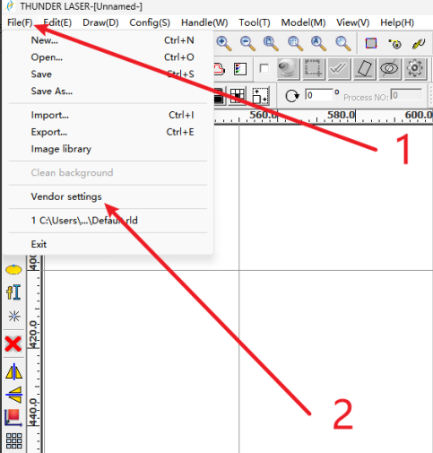
First connect the machine and RDWorks,then click "File" in RDWorks and enter "Vendor Settings" function. The password is RD8888 .
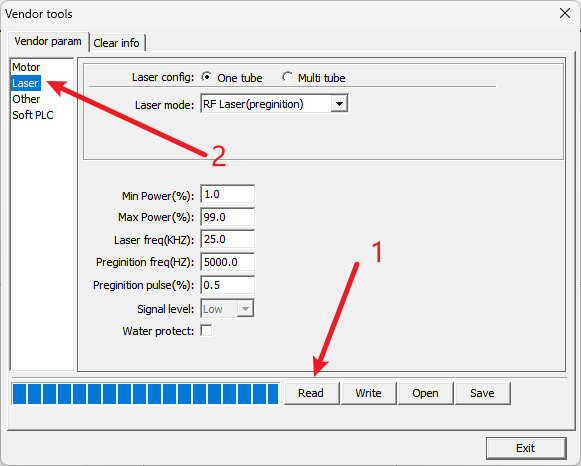
After clicking "Read" button, click "Laser" tab.
2. Set up laser config
- For Laser config, select "Multi tube".
- Select "Laser 1 type" to "Glass tube" .
- Select "Laser 2 type" to "RF Laser (preginition)".
- Make sure other config is same to screenshot below.
- Click "Write" and wait until progress complete .
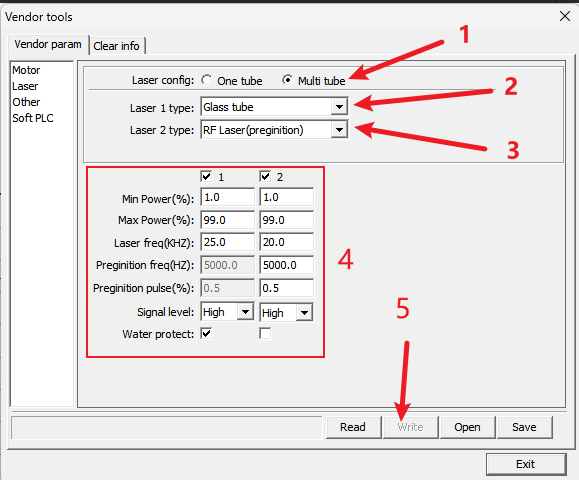
3. Click "Read Parameters" to confirm that the changes just made have taken effect.
Make sure that laser type 1 is glass tube and laser type 2 is RF tube CO2 (preginition)!
4. Check whether the equipment switches the dual laser source correctly.
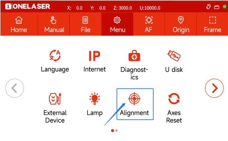
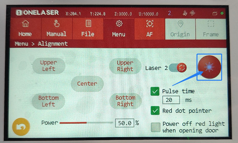
On the touch panel:
- Click Menu→Alignment→Set the Pulse Power to 20%→Click to switch the laser source, and the Laser 1 will switch to the Laser 2

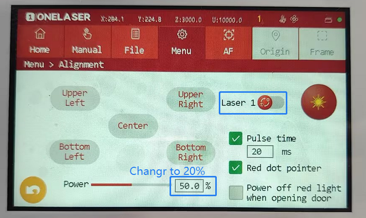
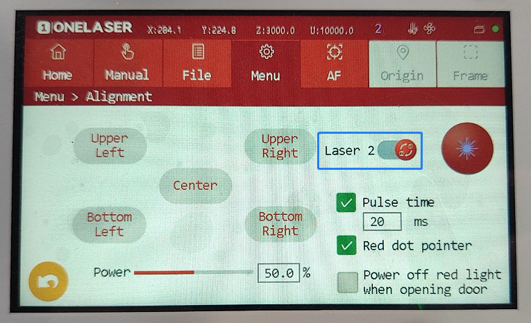
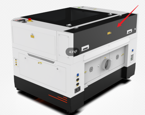
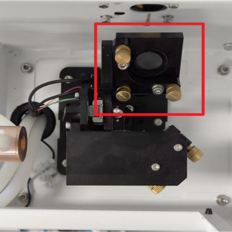
- Open the back cover of the device.We can see the reflector mirror will rise.
- Close the back cover after the mirror is raised, then please click the Pulse button on the panel to check if beam is emitted.
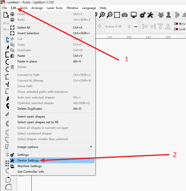
5. How to Switch Dual Laser Sources in Lightburn
First connect the machine and the machine.
Device Set up:
- In the Edit menu, click Device Settings
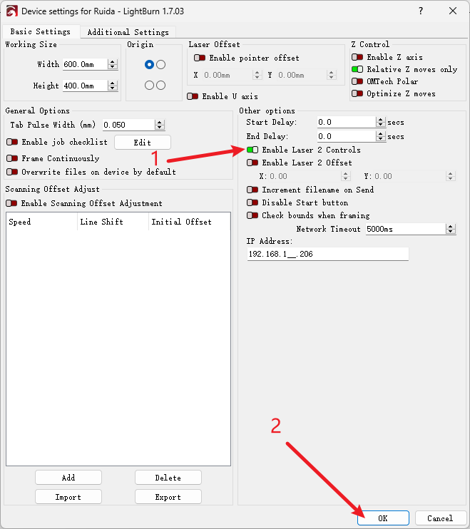
- Turn on "Enable Laser 2 Controls":
And make sure the "Enable Laser 2 Offset" switch is off and click OK.
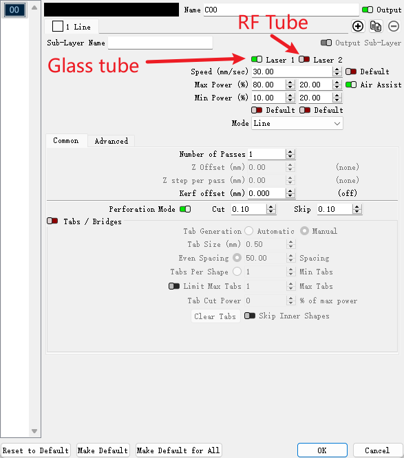
- Layer parameter settings
In the Layers menu:
"Laser 1" is the glass tube laser, and "Laser 2" is the RF tube laser.
Layers that require glass tube lasers: turn on "Laser 1"; turn off "Laser 2".
Layers that require RF tube lasers: turn on "Laser 2"; turn off "Laser 1".
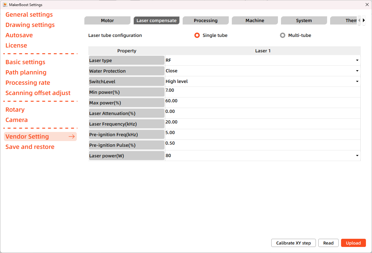
¶ 4.8.2 Hydra Gen 2
MakerBoost
First connect the machine and MakerBoost, then click "Settings" in MakerBoost and enter "Vendor Setting" function. The password is TL9501.
After clicking the "Laser compensate" button, select the "Read" tab. Laser parameters can be configured on this page.
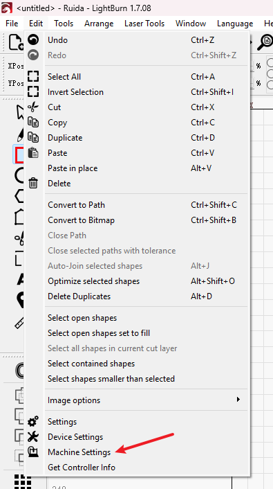
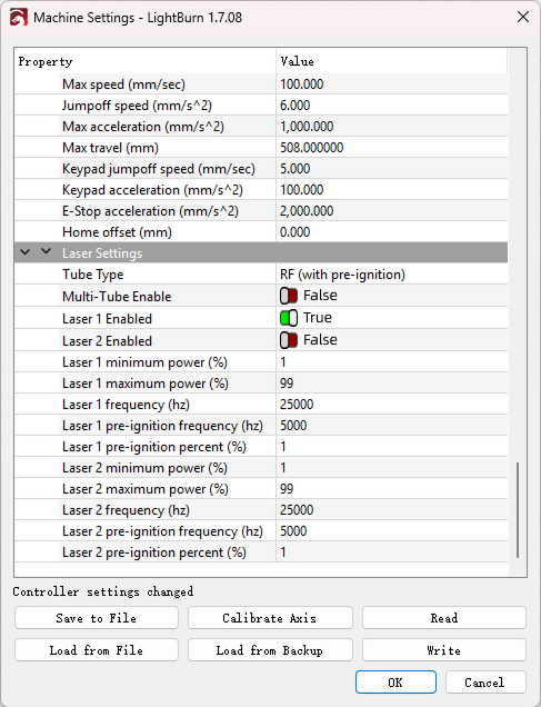
Lightburn
First connect the machine to Lightburn, then click "Edit" - "Machine Settings". Scroll to the bottom of the dialog window to configure laser parameters in the "Laser Settings" section.
¶ 4.9 The First Time Running the Laser
To be safe, never ever run the laser system unattended.
Yours first engraving tests
The following steps describe how to successfully engrave a first pattern. Please follow the individual steps:
1. Switch on the laser , then wait for a beep to note the machine is initialized, and the laser head will do the reset and find the home from top left corner.
2. After machine finish resetting, adjust the height of laser head, place the material usually on the top left corner of the working table.
①Move up the laser head;
②Place the material;
③Run auto focus or manual focus;
Please take care, if you are removing the honeycomb board for processing, please ensure that you place the material under the laser head before raising or lowering the laser head and performing auto-focus. Failure to do so may result in a collision.
3. Connect the machine with an USB cable or Ethernet cable or WIFI.
¶ 4.9.1 Engraving test
Before leaving the factory, each device undergoes professional calibration to ensure optimal performance. However, during transportation or relocation, pre-aligned components may shift slightly, affecting processing quality. Therefore, users should perform an engraving test before the first formal use.
MakerBoost
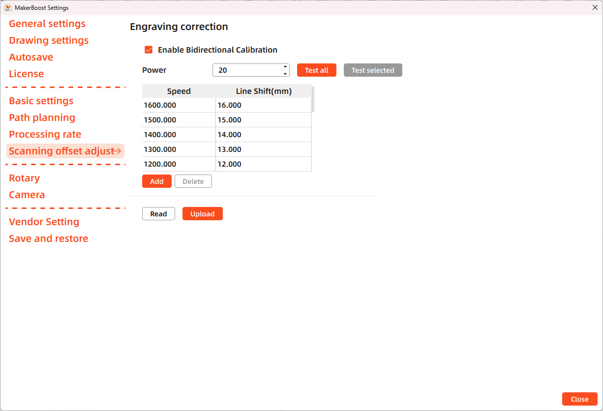
Open MakerBoost software. Click "Settings" in the top toolbar, then select "Scanning offset adjust" in the dialog window. The software will read existing parameters from the device. Click "Test all" to get results. If misaligned lines appear, measure the distance between both ends of the line at that speed and adjust the "Line Shift" parameter.
Lightburn
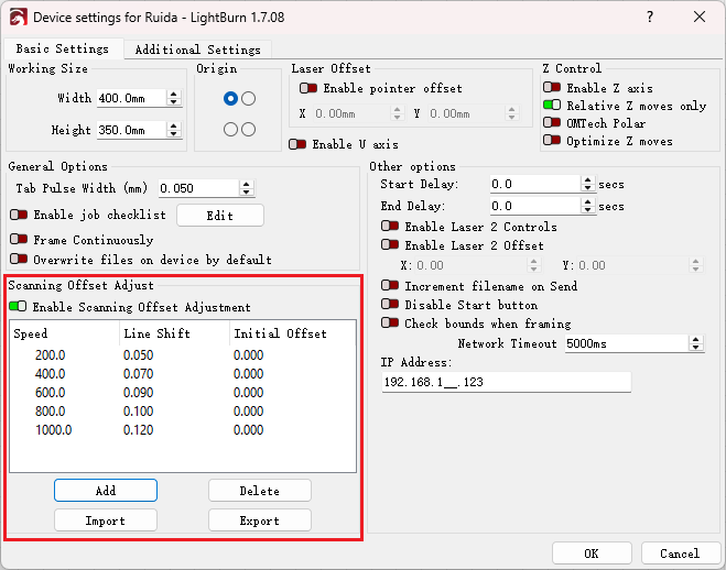
Open Lightburn software. Go to Devices Settings - Enable Scanning Offset Adjustment. Notice: Lightburn cannot read existing device parameters; users must manually enter values.
The particular values are showing with a picture in folder of laser software on the USB flash drive and on the Anodized aluminum piece that came with your machine.
¶ 4.9.2 Formal Engraving
After completing tests, you may formally operate the Hydra 70. Create any text, graphics, or images using MakerBoost or Lightburn. Then set up the parameter and download the file to your machine.
- Click "AF" to auto focus after placing the materials on working area.
- Click "Frame" button on the display, please make sure that the material is in the right location and there is enough space for working.
- Control arrow button to move the laser head;
- Click "Origin" button to select the start point;
- Click "Frame" button to be sure the working area;
- Finally press the "Start" button in the display, to start the engraving process.
After each operation, the laser head returns to its home position. Therefore, an auto-focus or manual focus is required before starting a new task.
When the engraving is complete, the laser machine will give out the notification sound and the laser head will go back to the original point, and the warning light will return to the green light, then you can repeat engraving. Please make sure the unit is in mm instead of inch.
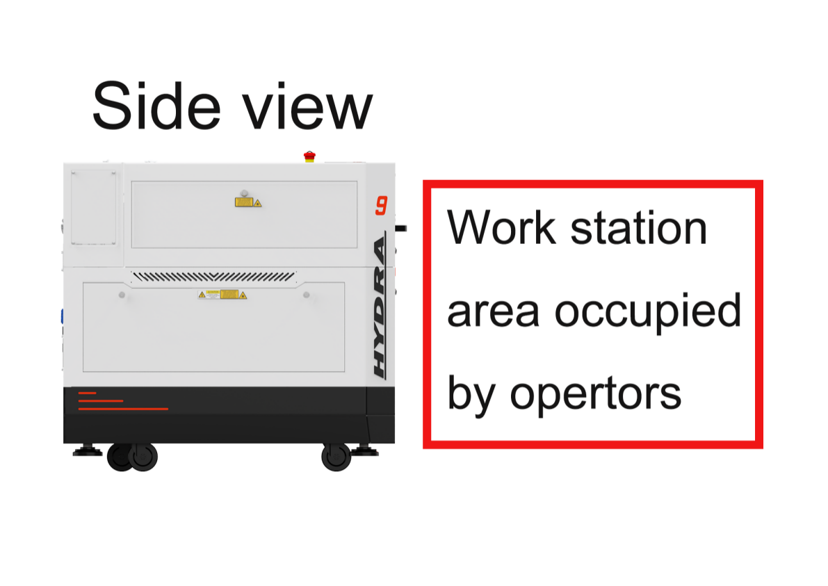
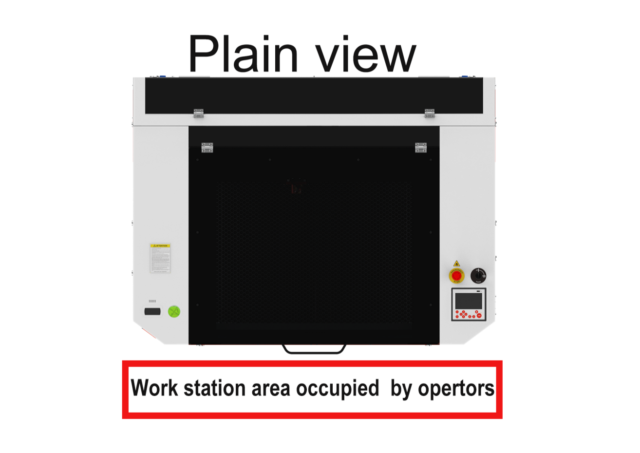
¶ 4.10 Workstation Area Indication
¶ 4.11 How to use the Chuck Rotary axis Attachment
- When the rotary switch is turned on, the rotary is controlled by the same driver as the Y-axis, rendering the Y-axis inoperable via panel control. However, manual movement of the Y-axis is still possible.
- Always turn off the rotary switch after use. Leaving it on will result in the machine getting stuck at the startup screen when powered on. Please turn off the rotary switch first, then click the reset button, and finally use it again.
- I mean OPEN;O mean CLOSE.
¶ 4.12 For Laser Engraving
The engraving depth can easily be varied through the laser power or the speed. To increase the engraving depth, reduce the speed or increase the power setting. This way you increase the amount of energy per area unit. Engraving too deep, however, reduces the quality of the details. With coated materials the required power depends of the kind and thickness of the coating. With power set too high the individual lines become too thick and a sharp picture cannot be achieved. The resolution of the graphics should usually be at 500 dpi. The dpi setting (number of laser dots per inch) depends on the material. The lower this setting is, the lower the resolution of the engraved picture will be. This, however, reduces flaming and increases the energy of a pulse, which can improve the overall result (e.g. when engraving some sorts of plastic materials).
1. Plastics
Plastics for engraving are available in many different colors and thicknesses and with many different coatings and surfaces. The majority of available plastics can be well engraved and cut with the laser. Plastics with a micro-porous surface seem to give the best result, because less surface material needs to be removed. As most plastic materials have a low melting point, a low pip setting should be selected to reduce the danger of melting.
2. Acrylic
There are two different types of acrylic – cast and extruded. The cast acrylic becomes white or mat after engraving, the extruded acrylic remains clear. Use extruded acrylic for engravings that are filled with paint and cast acrylic for normal engravings. Cast acrylic can be best engraved without protection foil. It is better to engrave the entire surface with a low energy setting.
3. Engrave the rubber stamp
The various mixtures and densities of rubber plates cause a slightly varying engraving depth. The settings in the overview table give a good indication. Since engraving a standard rubber material requires a relatively high laser power, the laser power is principally set to 40% or more high and only the speed is varied. Due to their lower density, so-called micro porous rubber materials allow a significantly higher engraving speed. Test the rubber first, to find out the correct speed setting.
The RDWorksV8 software using the engraving function, you can choose “Ramp Effect” or common engraving, once you choose “Ramp Effect” and you will need to set a minimum power lower than Max Power, generally we set it to about 15%, and input a value with the Ramp Length what you want, but if you want to make it better, you may need to test different kinds of power and speed by yourself, then you can get the best result.
Engraving rubber produces a considerable amount of dust and terrible gas. Therefore a well-dimensioned exhaust system and its regular maintenance are very important.