¶ Camera Calibration Guide
¶ Introduction
In general, camera lenses are not perfectly flat, which leads to image distortion. This effect is especially noticeable with fisheye lenses used to capture large laser working areas (which is the case for OneLaser machines).
To ensure proper camera functionality, calibration is required to compensate for this distortion. Although the calibration process takes some time, once completed, the calibration file can be exported and saved, eliminating the need for frequent recalibration.
OneLaser machines are preloaded with corresponding camera calibration files at the factory. You can find these files on the USB drive included with the machine and import them into LightBurn for normal use.
However, due to uncontrollable factors such as transportation, if the camera does not function properly after importing the file, please follow the methods below to recalibrate the camera. If you encounter any issues, contact OneLaser official support.
¶ Notes
- Calibration and alignment are both essential for proper camera setup. Each method includes two steps:calibration must be followed by alignment.
- Please download the required calibration files (see LightBurn official documentation for details):
- AprilTags in PDF or LBRN2 format (recommended)
- CalibrationCircles.png
Print the image and attach it to a rigid, flat surface such as cardboard, acrylic, or wood.
¶ Method 1: Calibrate Camera Lens + Calibrate Camera Alignment
¶ 1. Calibrate Camera Lens
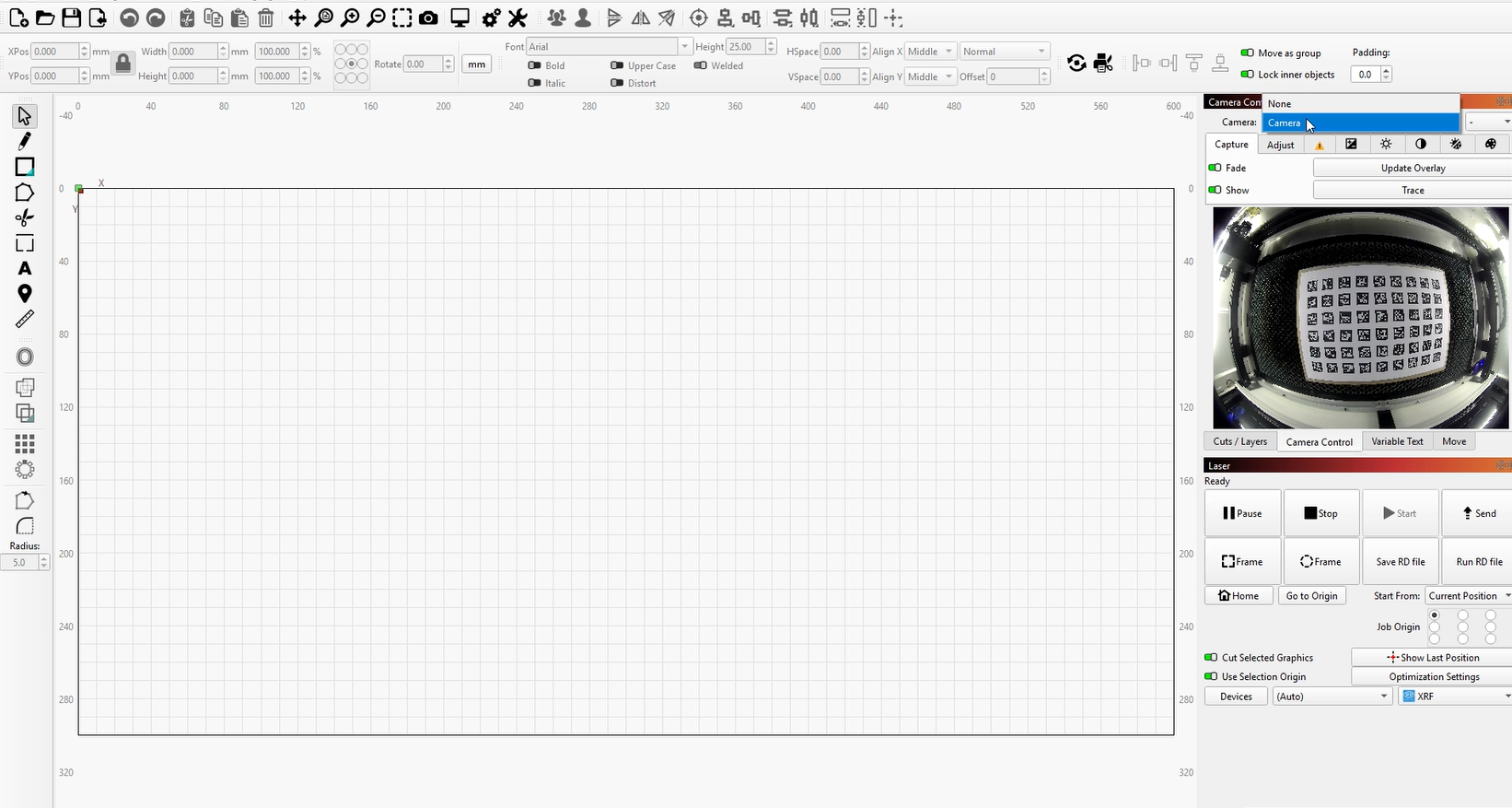
- Ensure the correct camera is selected in the Camera Control window.
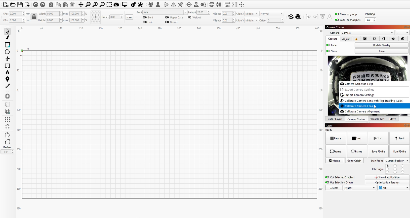
- Right-click and select “Calibrate Camera Lens.”
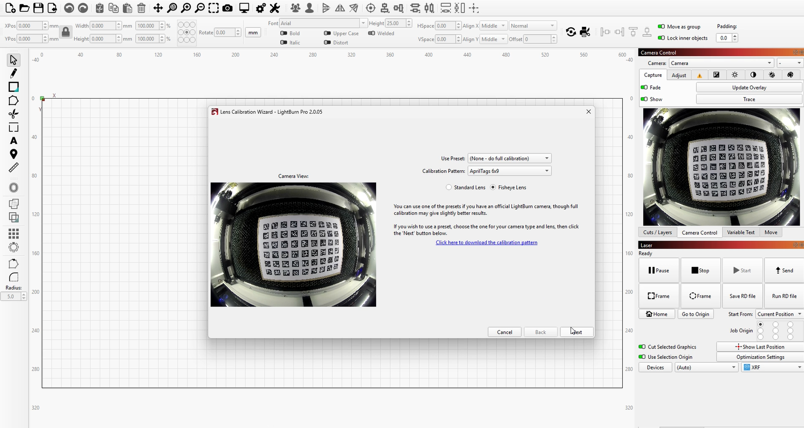
- Select the appropriate preset and choose the fisheye camera, then click “Next.”
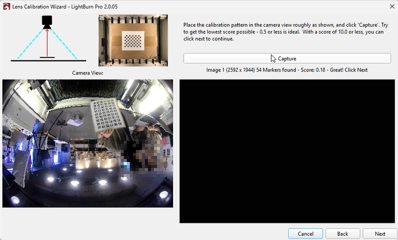
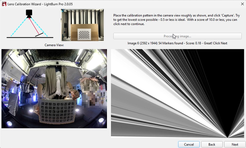
The interface will update, showing a Capture button and placement instructions. - If you have not prepared the calibration pattern in advance, you can print it at this step.
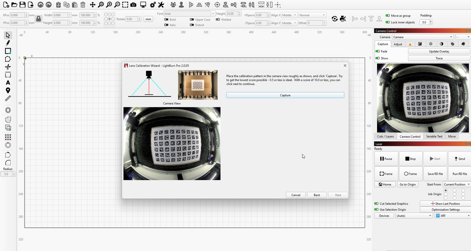
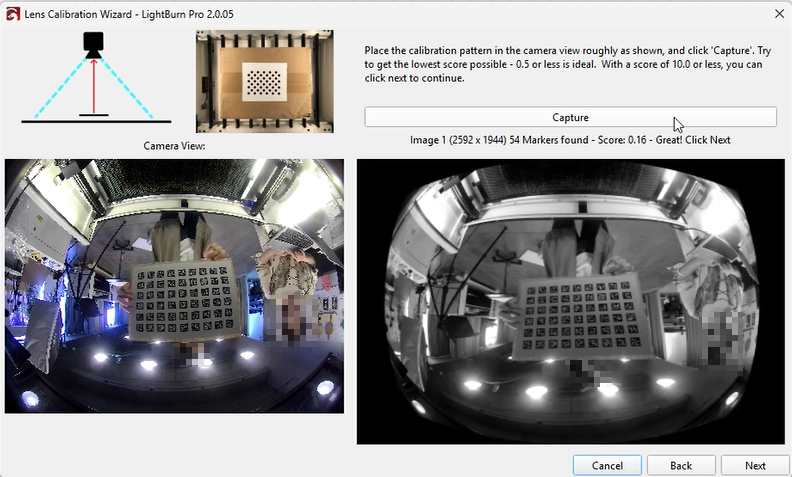
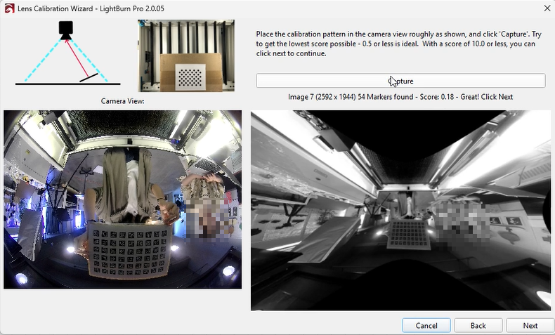
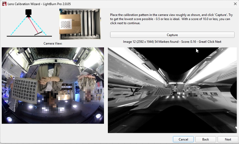
- Place the printed pattern according to the diagrams shown on screen.
Important: For shots near the edge of the camera view, position the pattern close to the edges (where distortion is strongest) to improve calibration accuracy.
- A lower score is better, as it represents lower average pixel error.
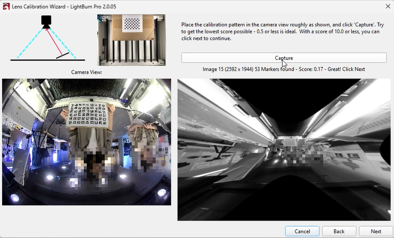
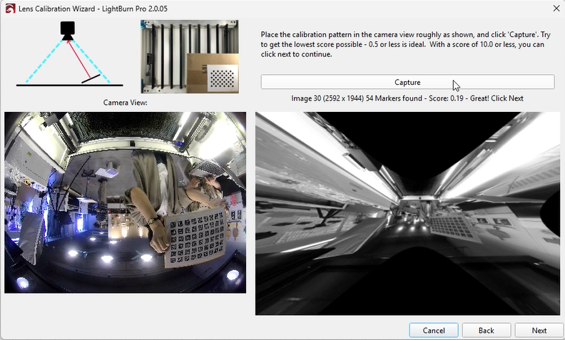
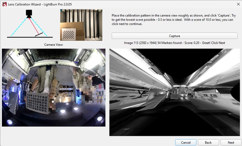
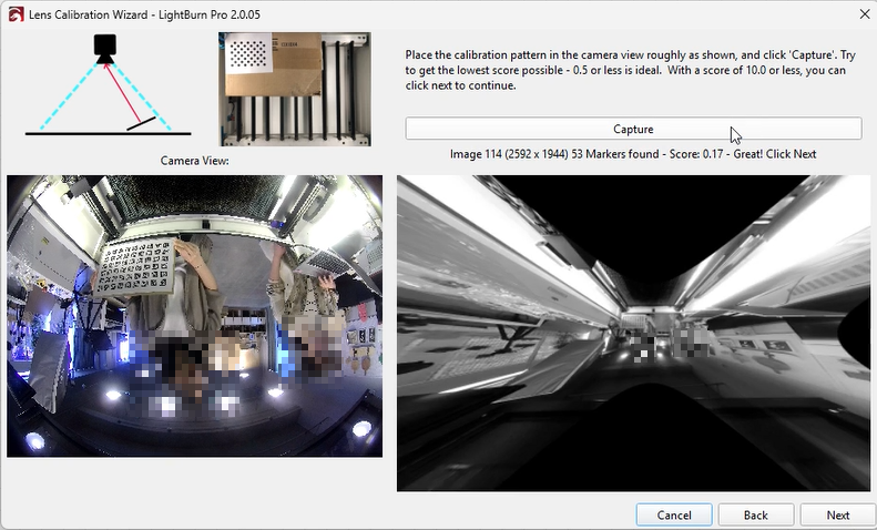
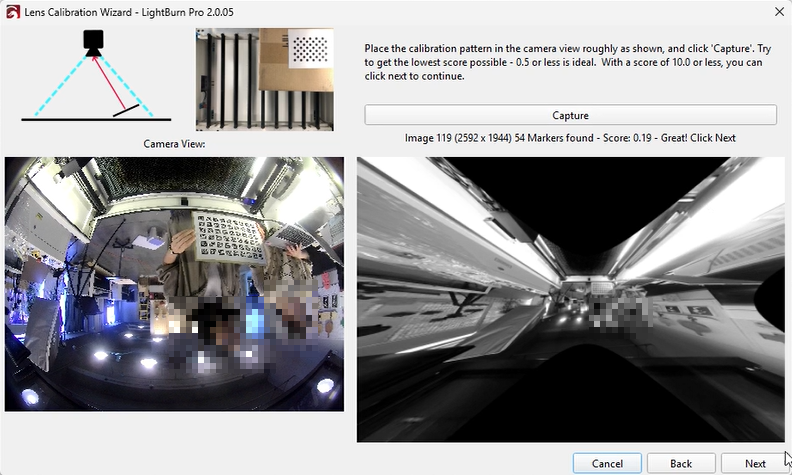
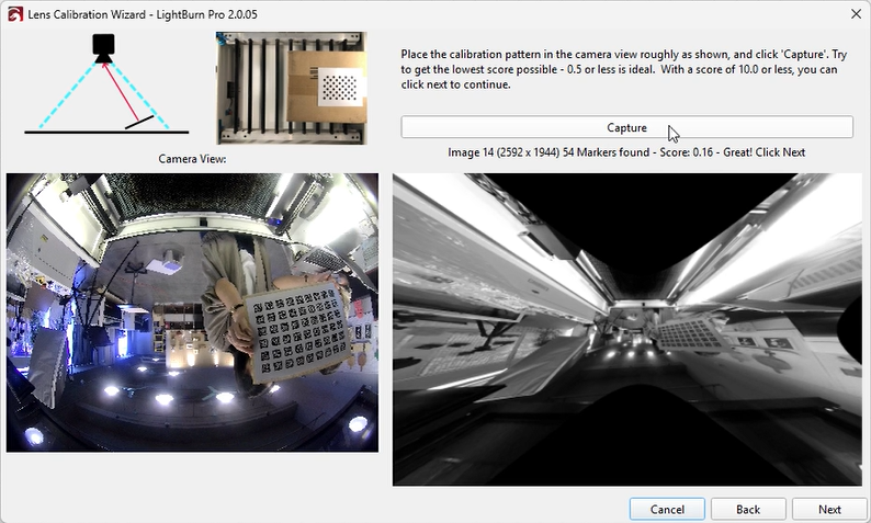
- If the capture fails or looks incorrect, do not worry—capture multiple times until a valid image is obtained.
- After calibration is complete, click “Next” to proceed to alignment.
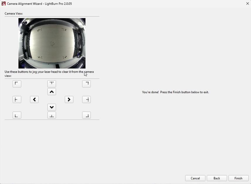
¶ 2. Calibrate Camera Alignment
- Prepare a material such as cardboard, wood, or acrylic to engrave the alignment pattern, and mark the center of the target.
- Click “Fit Workspace” to scale the pattern to match the laser working area.
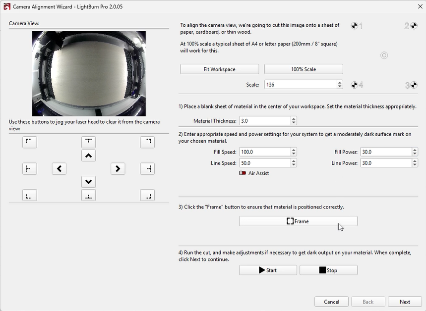
- Set appropriate laser speed and power to produce a visible mark without cutting through the material.
(Settings vary depending on machine and material; the example shown is for thin wood.)
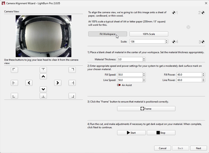
- Run a “Frame” preview to ensure correct positioning on the material.
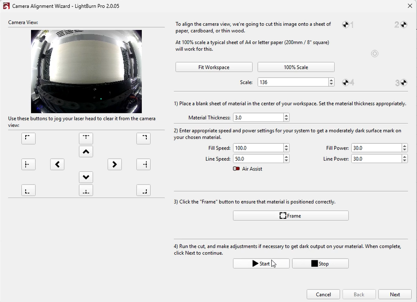
- Start engraving. If the marking is too light, adjust settings and repeat.
Once the pattern is clearly visible, click “Next.”
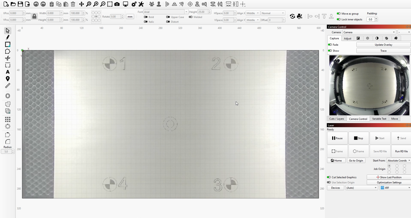
- Capture the alignment image.
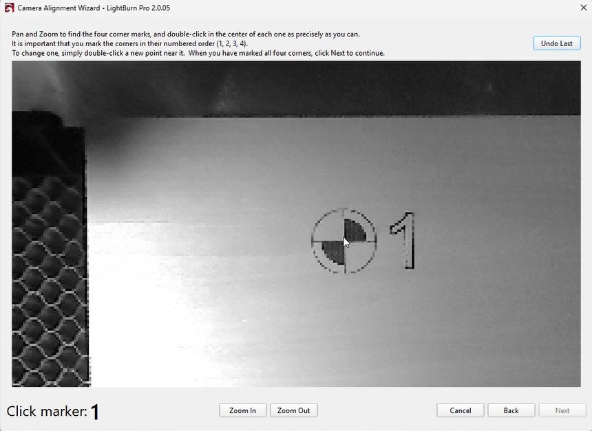
When all four targets are clearly visible, click “Capture Image.”
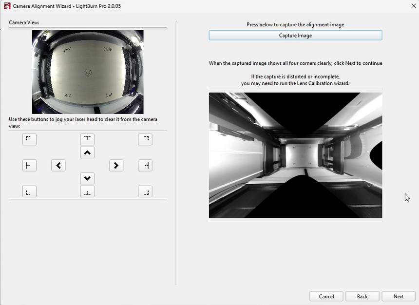
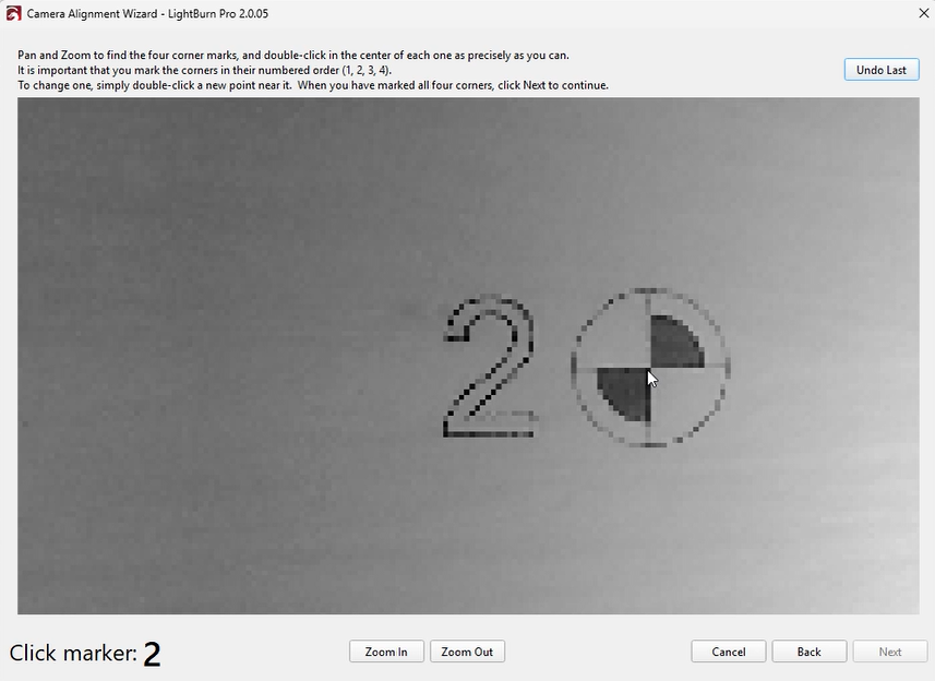
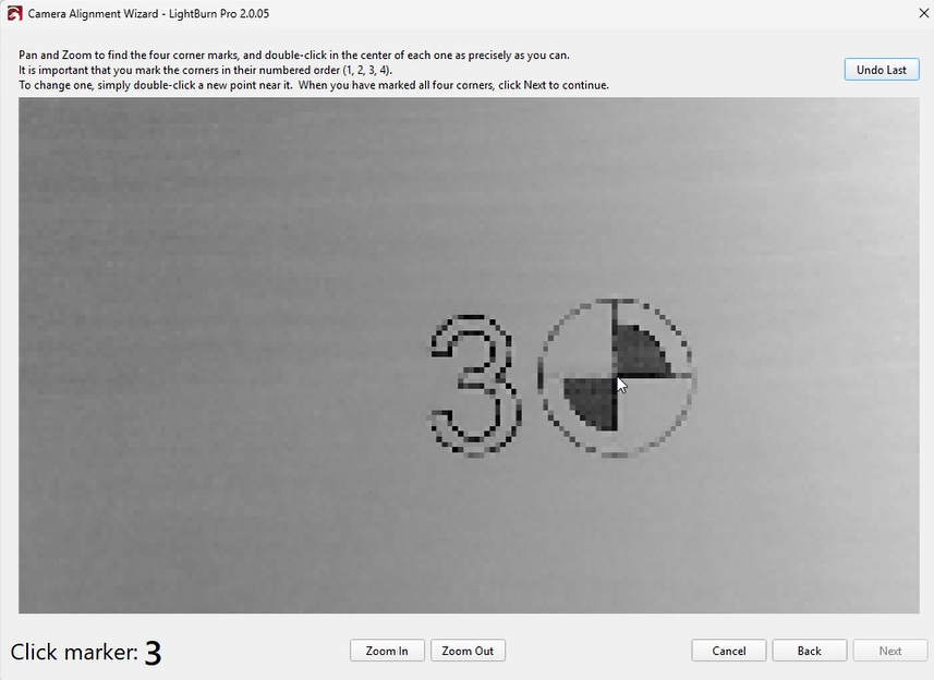
- Mark each target by double-clicking its center.
You may zoom or pan the image as needed. - A red “+” marker will appear after each double-click.Place markers in order (1, 2, 3, 4) at the center of each target.
If a marker is misplaced, double-click near it to reposition or click “Undo Last” to remove it. - Place all markers as accurately as possible.
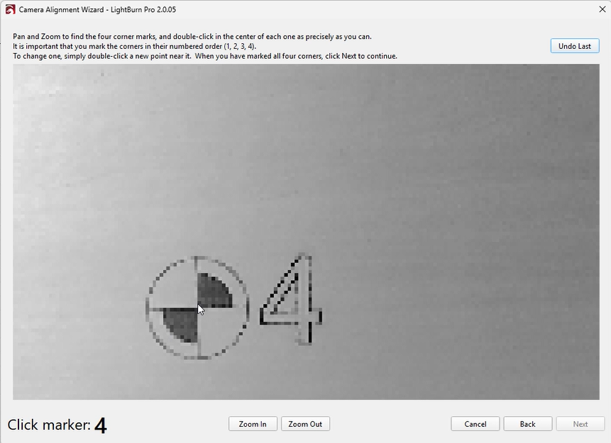
- Click “Next,” then “Finish” to complete the process and save the results.
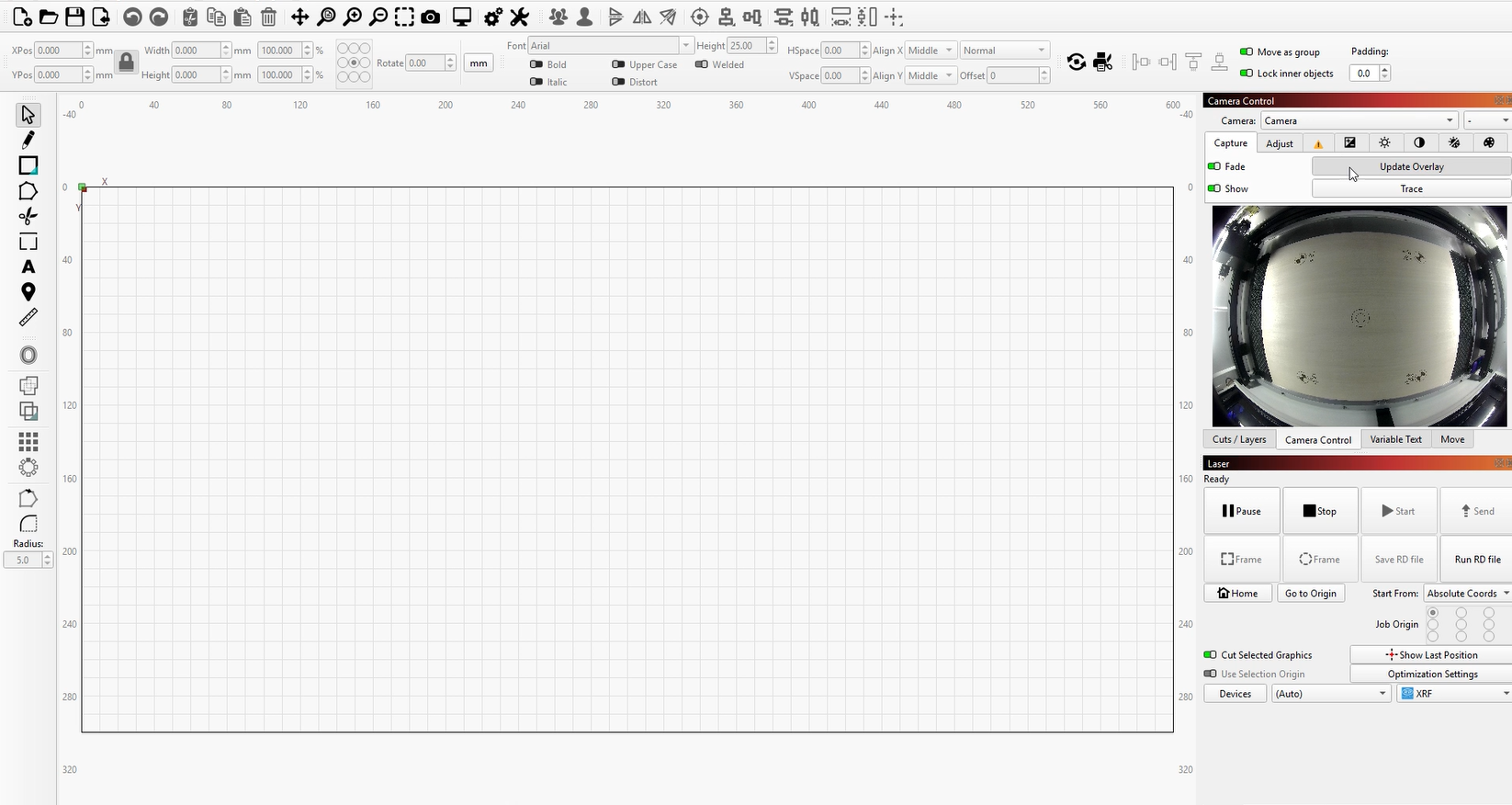
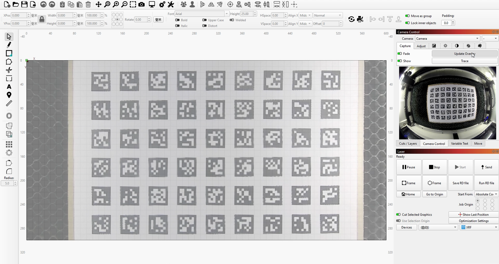
¶ 3. Update Overlay
- Return to the workspace and click “Update Overlay” or press Alt / Option + C.
This captures the camera view and overlays it onto your workspace.
¶ Method 2: Calibrate Camera Lens (Labs) + Calibrate Camera Alignment
¶ 1. Calibrate Camera Lens (Labs)
- Download and print the AprilTag calibration pattern, and mount it on a rigid, flat surface.
- In the Camera Control window, ensure the correct camera is selected.
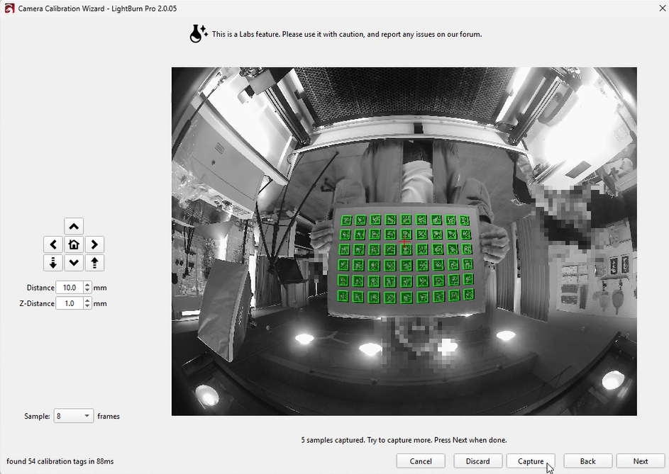
Right-click and choose “Calibrate Camera Lens with Tag Tracking (Labs).”
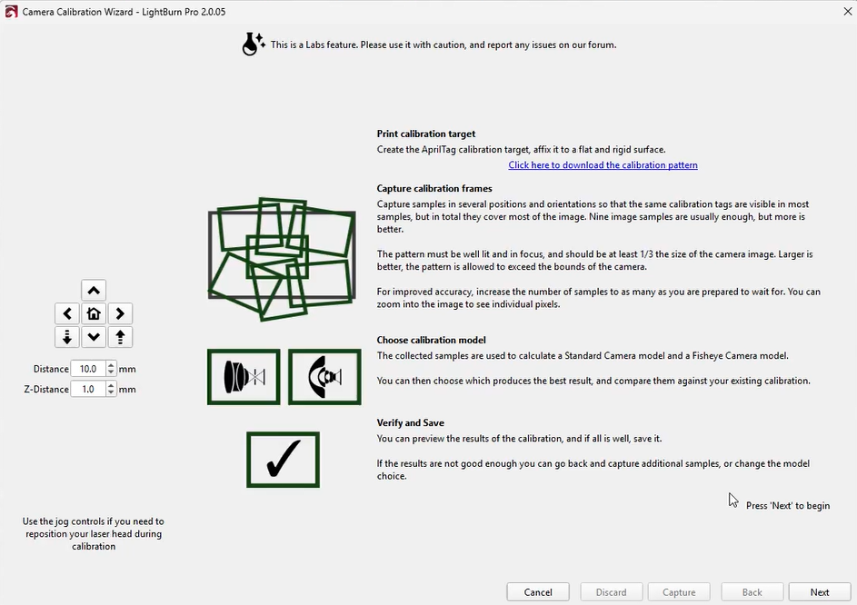
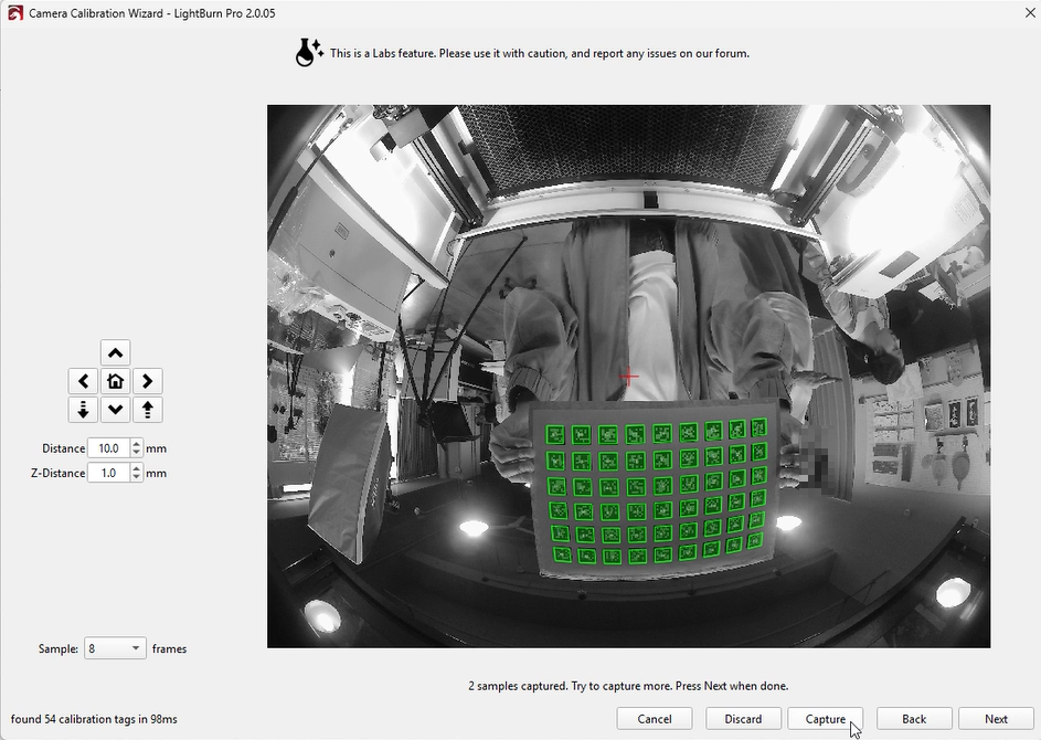
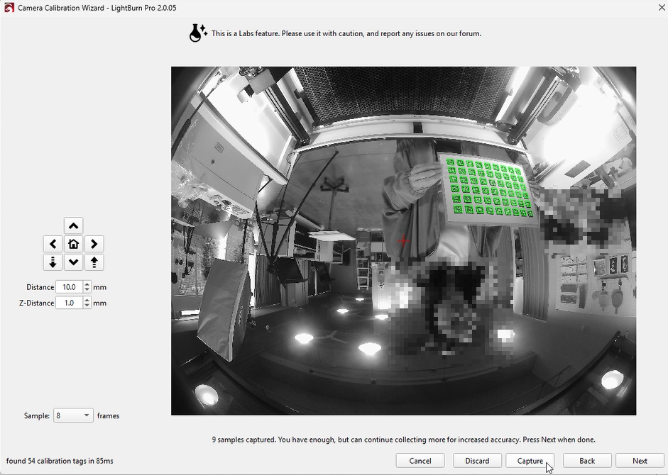
- Click “Next.” A live camera feed will appear along with additional controls.
- The system will detect AprilTags and overlay green squares on them.
Adjust the pattern position so that as many tags as possible are visible.
Note: If few or no tags are detected, adjust the camera focus.
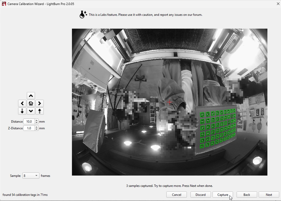
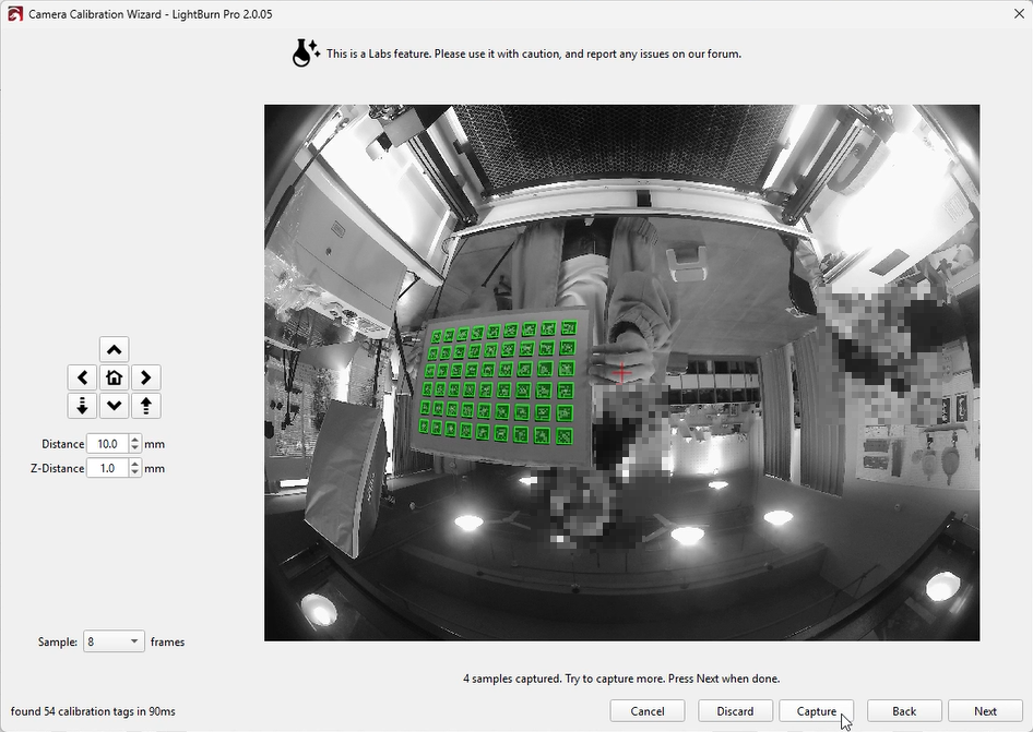
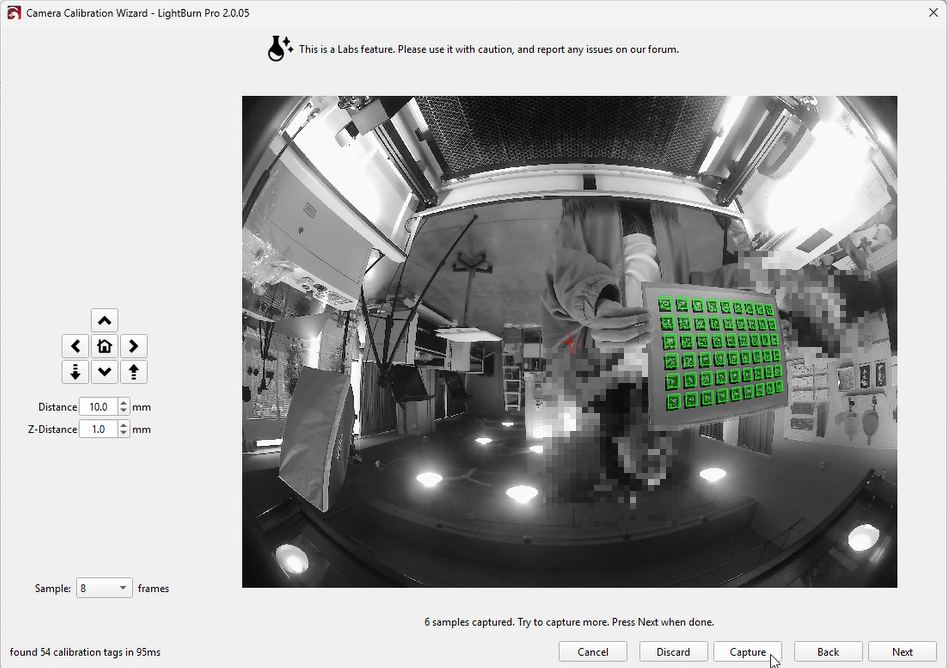
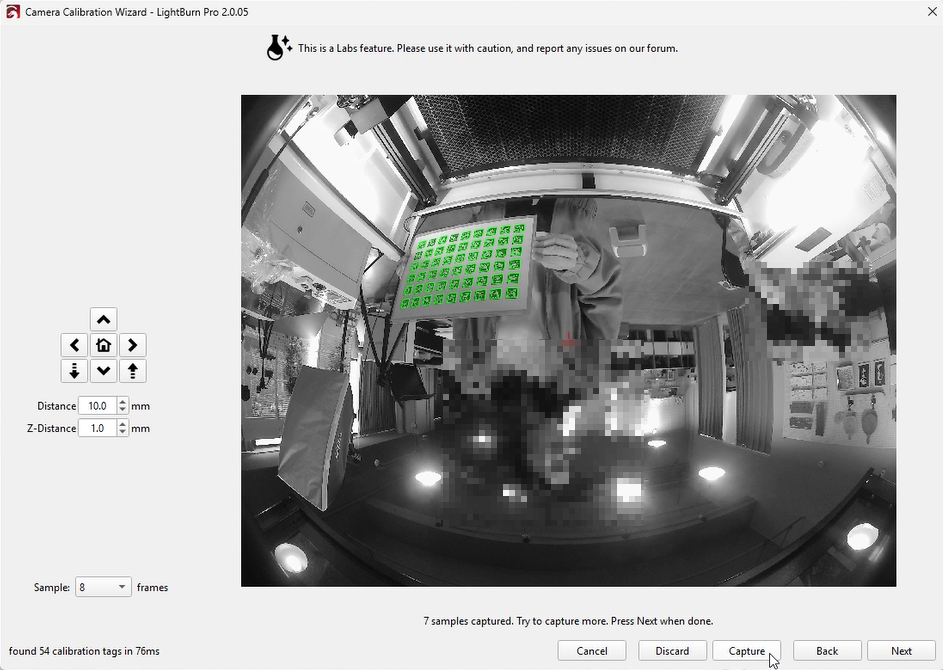
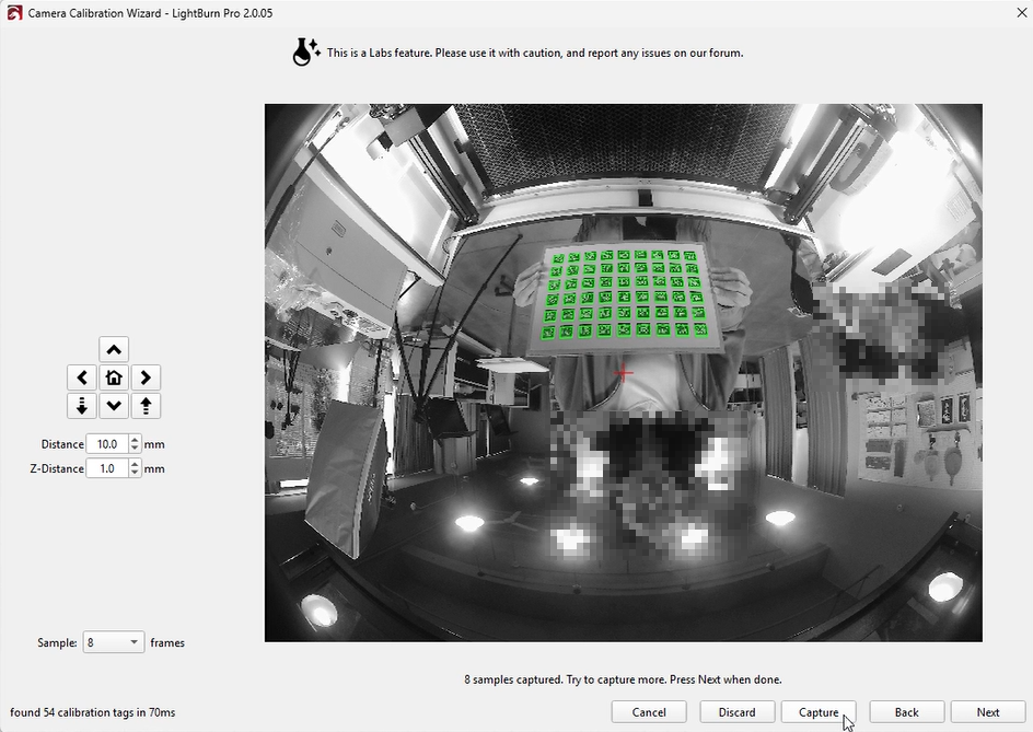
- Click “Capture.”
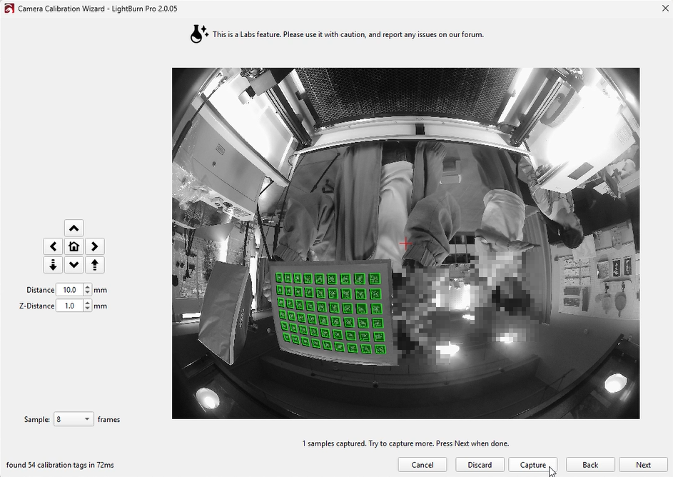
- Move and rotate the calibration pattern within the camera’s field of view, capturing images at different positions.
- The system will build three models:
- Use the dropdown menu to compare results.
The better model will show less distortion. - You may also select “Original Calibration” for comparison.
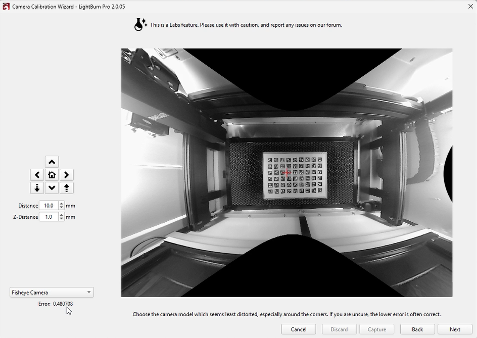
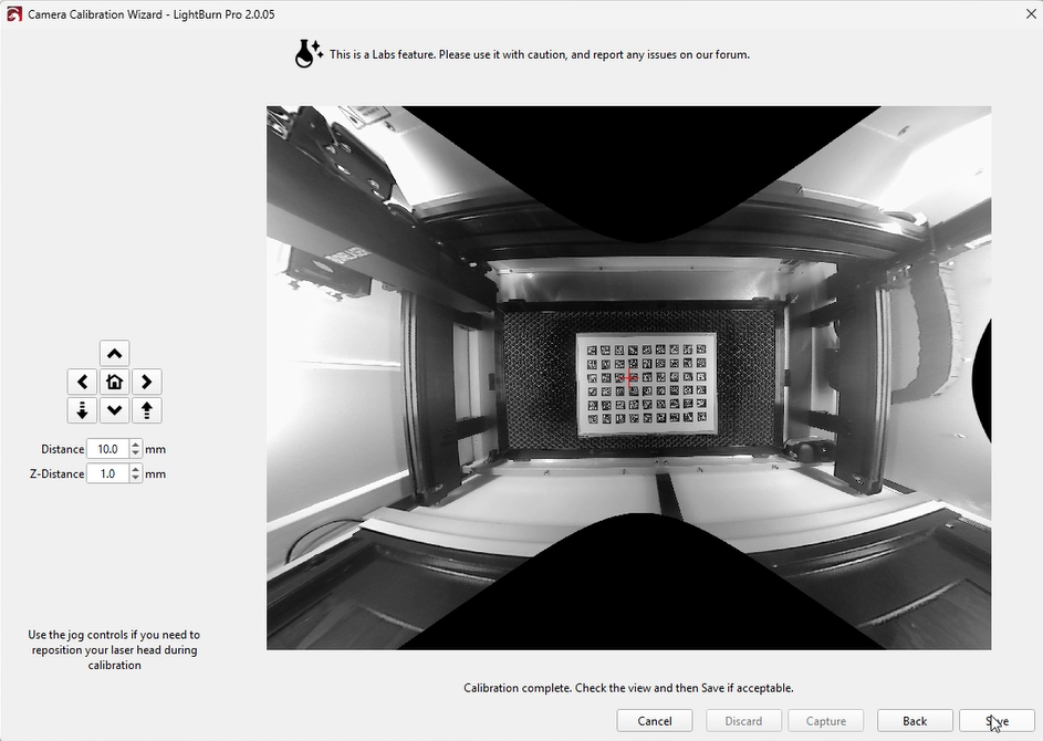
- Choose the model with the least distortion, then click “Next.”
- If satisfied with the result, click “Save.”
¶ 2. Calibrate Camera Alignment
- Return to the workspace.
- In the Camera Control window, right-click and select “Calibrate Camera Alignment.”
- The steps are the same as in Method 1.
¶ 3. Update Overlay
- Return to the workspace and click “Update Overlay” to project the camera view onto the workspace.
¶ Notes
- Based on internal testing, Method 1 provides higher accuracy and is therefore recommended.
- This guide is based on the XRF model. Due to the camera-to-platform distance, calibration was performed with the lid open and the board elevated.
For Hydra models, you can close the lid and place the board directly on the platform. - Camera calibration is sensitive to movement. Even slight shaking can introduce errors.
It is recommended to perform calibration with two people or use a stable fixture. - Although LightBurn suggests an error below 0.5 is acceptable, this is near the upper tolerance limit.
Based on our testing, achieving an error below 0.2 will provide significantly better calibration results.