¶ 4.1 Machine View
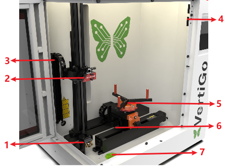
1.Mirror
The laser beam is reflected by the mirror to the laser head.
2.Laser Head
Laser beam and red dot pointer are all come
out from the laser head.
3.Drag Chain
Protects and guides cables in moving machinery.
4.Door Protection Sensor
Laser will stop working once the cover is opened during working. The sensor is also installed in the same place on the left side.
5.Rotary Fixture
This is used to clamp the workpiece and utilize the rotating function to complete engraving.
6.Z Axis (left and right movement)
The motion system is that performs the
mechanical movements in Z direction.
7.Spirit Level
The spirit level is used to indicate whether the device is balanced and can be used when using a caster to adjust the level.
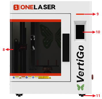
8.Flap
If the flap is opened, no data is processed. When the protection cover is opened during working, the motion system is stopped and the laser source is turned off. During processing of commands the protection cover must only be opened after pressing the “Pause” button.
9.Indicator Light
A green light illuminates when the machine is operating.
10.Control Panel
You can control the X-axis, Z-axis and U-axis manually by the display panel, it also shows the working time, power, speed and the whole working time and affords many function options.
11.Caster
The casters facilitate the movement of the device and are used to adjust the balance of the device.
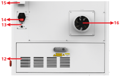
12. Cooling Fan
Cooling the Internal components.
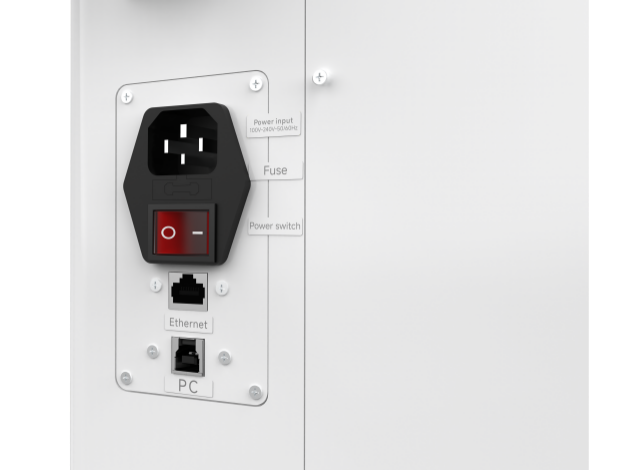
13.PC and Ethernet Connection Port
Connect machine with PC cable and Ethernet cable.
14.Main Switch
Power on or off the machine.
15.WiFi Router
Used to receive WiFi signals.
16.Exhaust Fan
Connect the exhaust pipe.
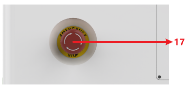
17.Emergency-stop
Once there’s an accident happen (laser catch fire, laser out leakage) during working, please turn off this switch immediately. It will be cut off the laser power and motion power immediately.
¶ 4.2 ON/OFF Switch
MUST confirm these conditions BEFORE powering on the equipment:
1. Clear the work area: Remove all materials and foreign objects from the worktable and laser head travel paths to prevent collision damage during homing.
2. Secure enclosures: Ensure all doors and access panels are closed and secured.
3. Verify auxiliary systems: Confirm exhaust/cooling systems are operating normally.
Startup Sequence:
4. Press the Power Switch to ON position.
5. The control panel will initialize while the laser head performs homing.
6. When the home screen appears, the system is ready for operation.
¶ 4.3 Make Connection between PC and Machine
¶ 4.3.1 Software Installation
MakerBoost
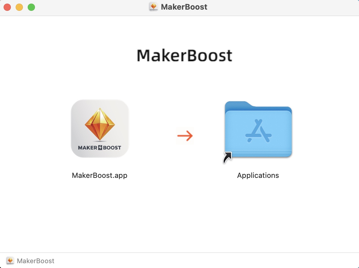
Mac:
Click to download the file. Drag the software on the left into the folder on the right. The software has been downloaded successfully. You can find it in the Launchpad and use it.
Win:
During installation, check the box for "Install device USB driver". Wait for the driver to download automatically. Finally, click "Finish" to complete the installation.
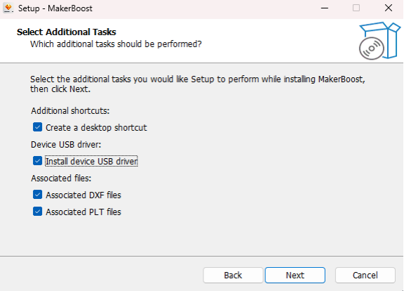
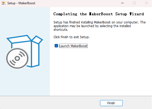
The "MakerBoost" desktop icon will be created automatically. The software is now ready for use.
Lightburn
Please download the corresponding Lightburn at the link below:
https://lightburnsoftware.com/pages/download-trial
If you use USB cable connection, please install the USB driver.
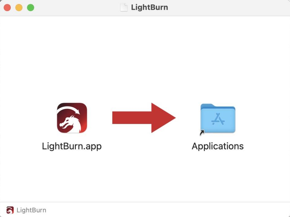
Mac:
Click to download the file. Drag the software on the left into the folder on the right. The software has been downloaded successfully. You can find it in the Launchpad and use it.
Win:
After selecting your options, click "Finish" and then wait for the driver download to complete. You can confirm this and then end the installation process.
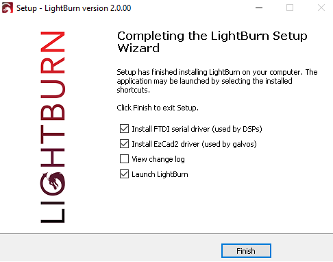
A "Lightburn" icon will be automatically added to your Desktop, you are now ready to use the Lightburn.
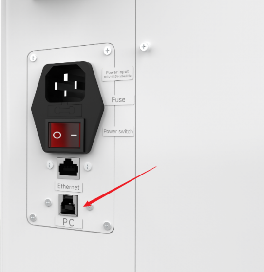
¶ 4.3.2 Wired Connection
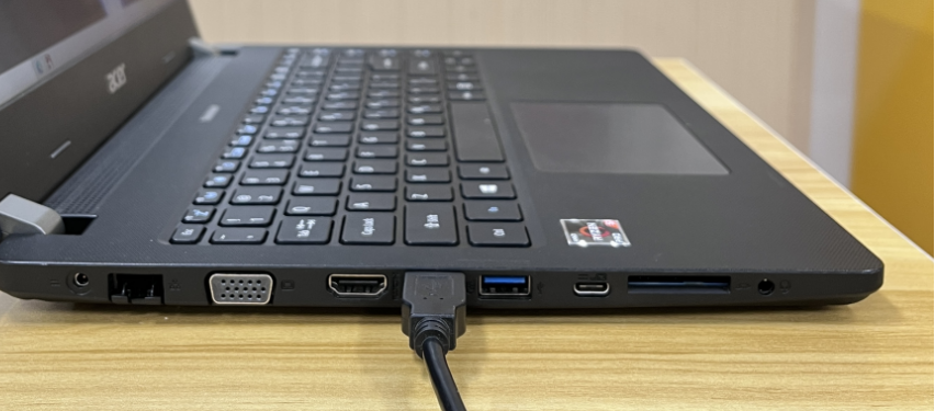
USB Cable Connection
Connecting the Computer and the machine by using the USB cable. Like below (Please use a docking station or adapter to connect for MacOS):
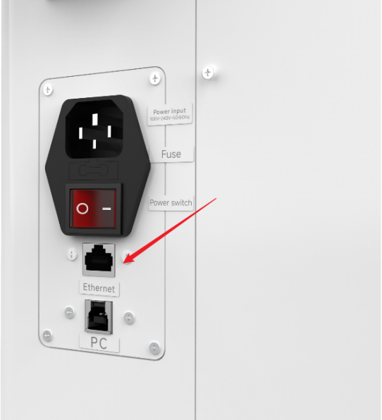
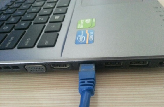
Ethernet Cable Connection
Connecting the Computer and the machine by using the Ethernet cable. Like below (Please use a docking station or adapter to connect for MacOS):
To establish communication between the PC and machine via the above methods, follow these steps:
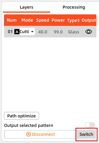
MakerBoost
Make sure that you have your PC connected to the machine via USB cable or Ethernet cable.
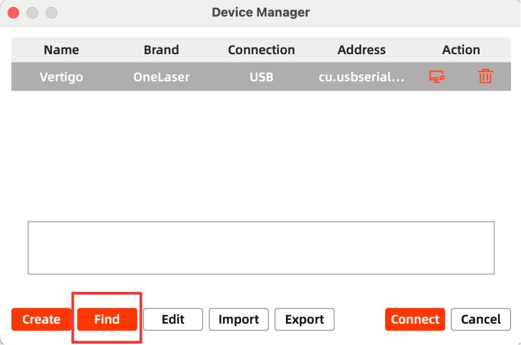
Click "Switch" from right bottom corner of the software, then click "Find" to set up by the Devices setting.
Mac:
Win:

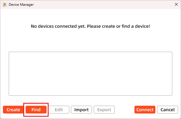
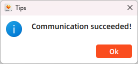
Then follow instructions to complete the connection steps step by step. Select the connection you just created and the display shows "Communication Succeeded" to indicate a successful connection. Now MakerBoost communicates with your laser machine via USB cable or Ethernet cable.
Lightburn
Make sure that you have your PC connected to the machine via USB cable or Ethernet cable.
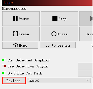
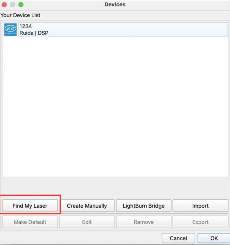
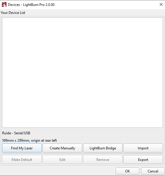
Click "Devices" from right bottom corner of the software. Click "Find My Laser" to set up by the Devices setting.
Mac:
Win:

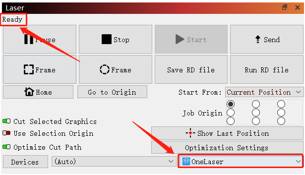
Then follow instructions to complete the connection steps step by step. Select the connection you just created and the display shows "Ready" to indicate a successful connection. Now Lightburn communicates with your laser machine via USB cable or Ethernet cable.

When connecting the machine and the PC for the first time, it may take a few minutes for the operating system to recognize the machine and install the driver.
¶ 4.3.3 Remote Connection
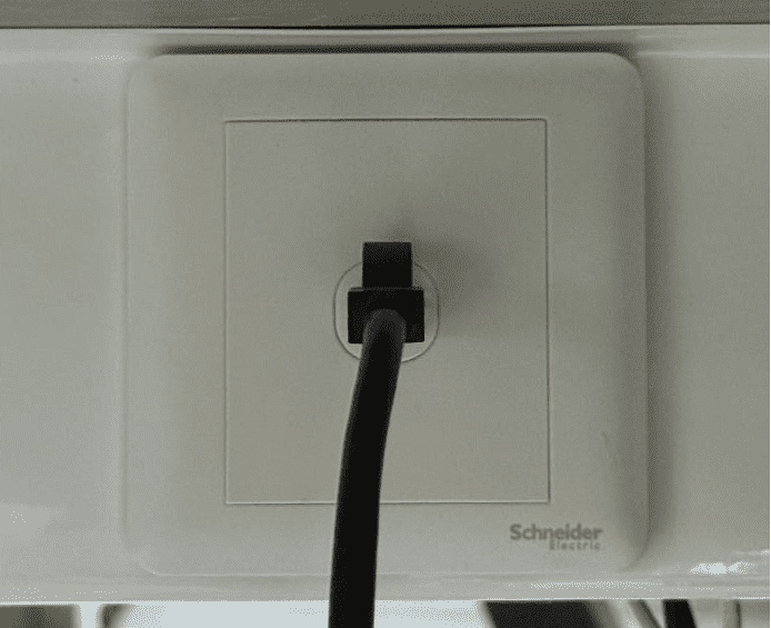
Network Cable Connection
Connect both the VertiGO and computer to the network using Ethernet cables.
Critical: Ensure they reside on the same subnet (e.g., 192.168.1. XXX).
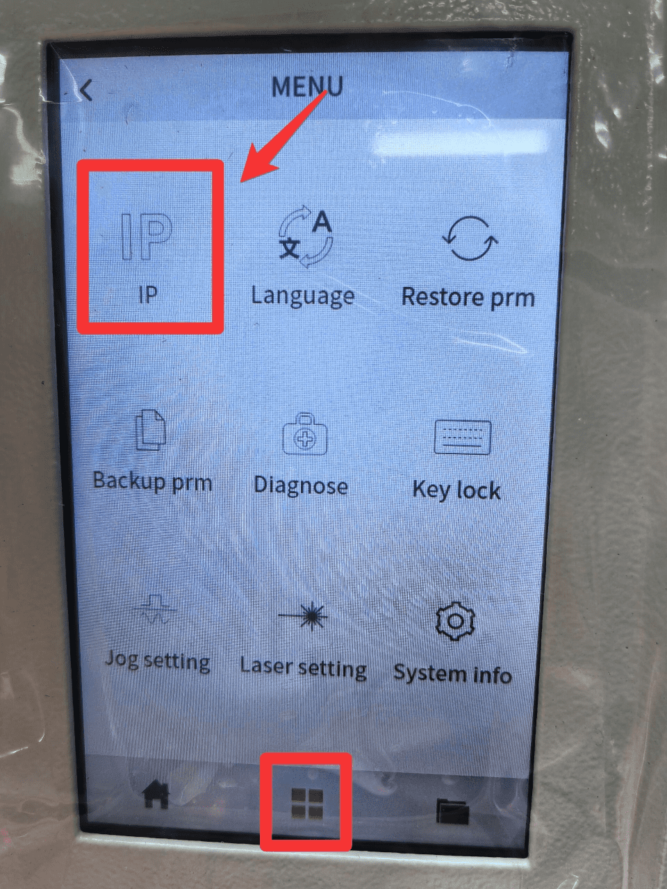
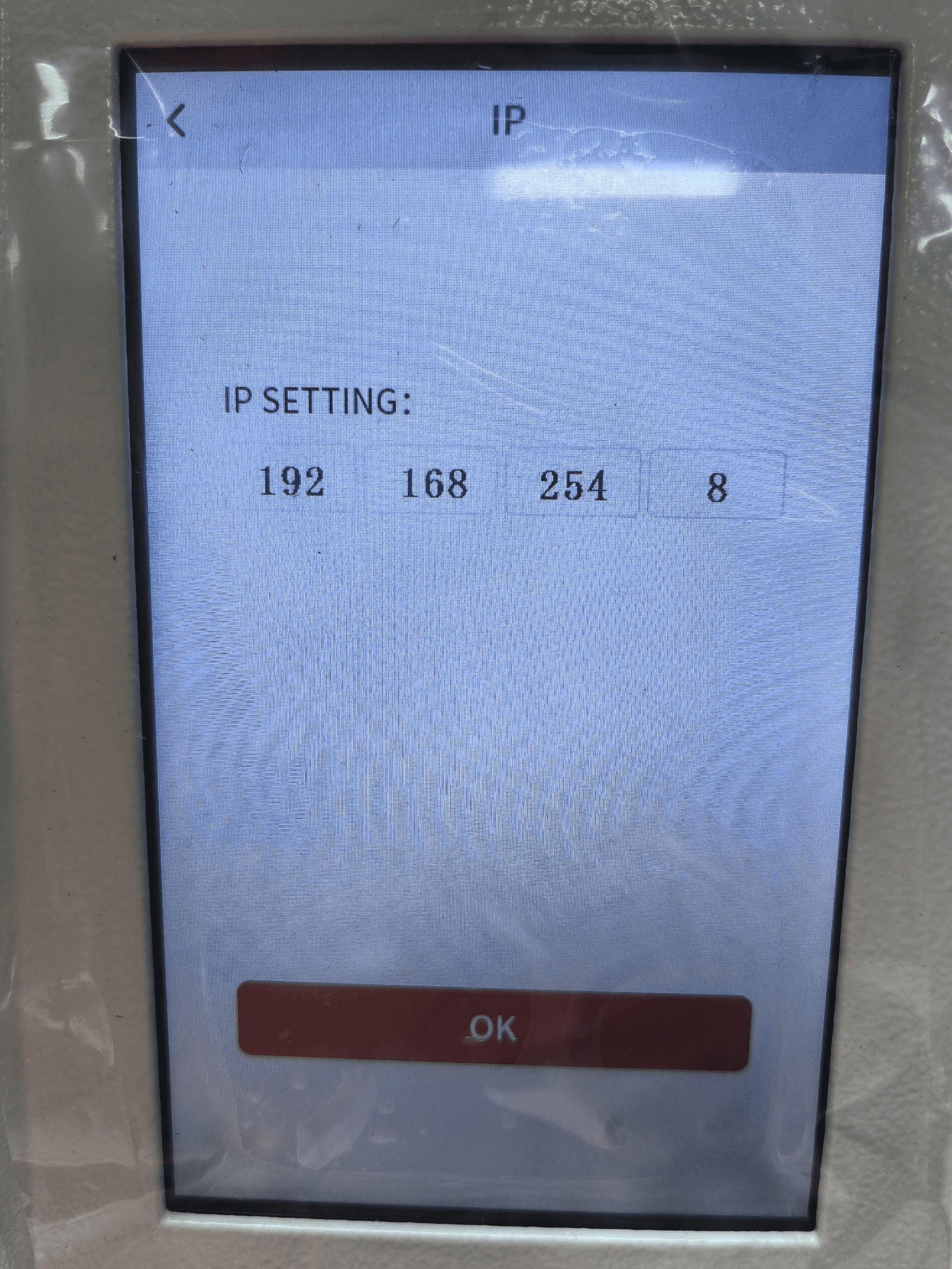
How to Viewing/Modifying VertiGO IP Address?
To establish communication between the PC and machine via the above methods, follow these steps:
MakerBoost
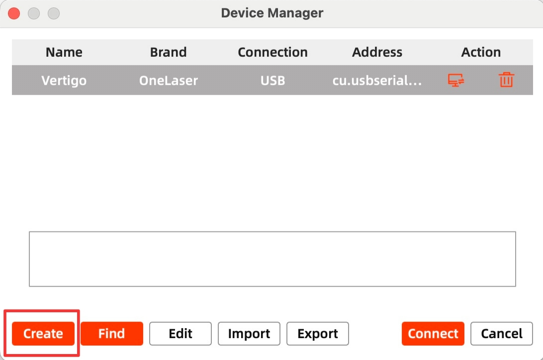
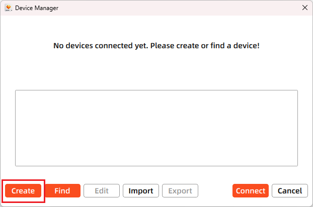
Click "Switch" from right bottom corner of the software, then click "Create" to set up by the Devices setting.
Mac:
Win:
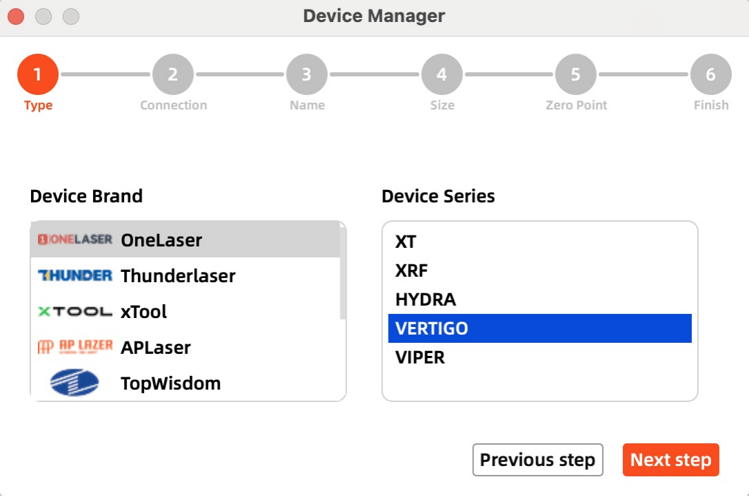
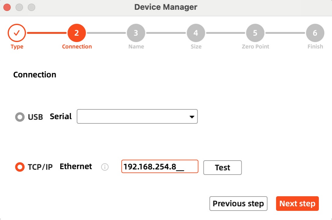
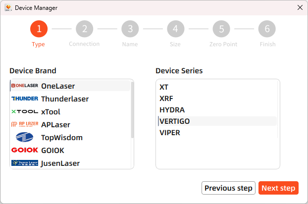
Then follow instructions to complete the connection steps step by step.
Critical: The entered IP MUST exactly match the VertiGo's configured address.
Mac:
Win:
After successful device creation, select the newly created "VertiGO" entry in the machine list. Then click the "Connect" button. The software will instantly activate the connection.
Lightburn
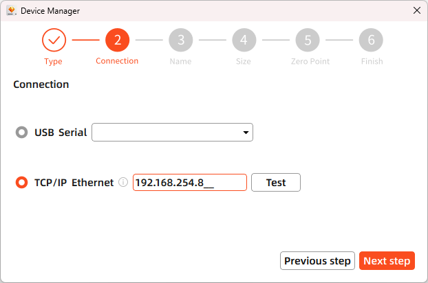
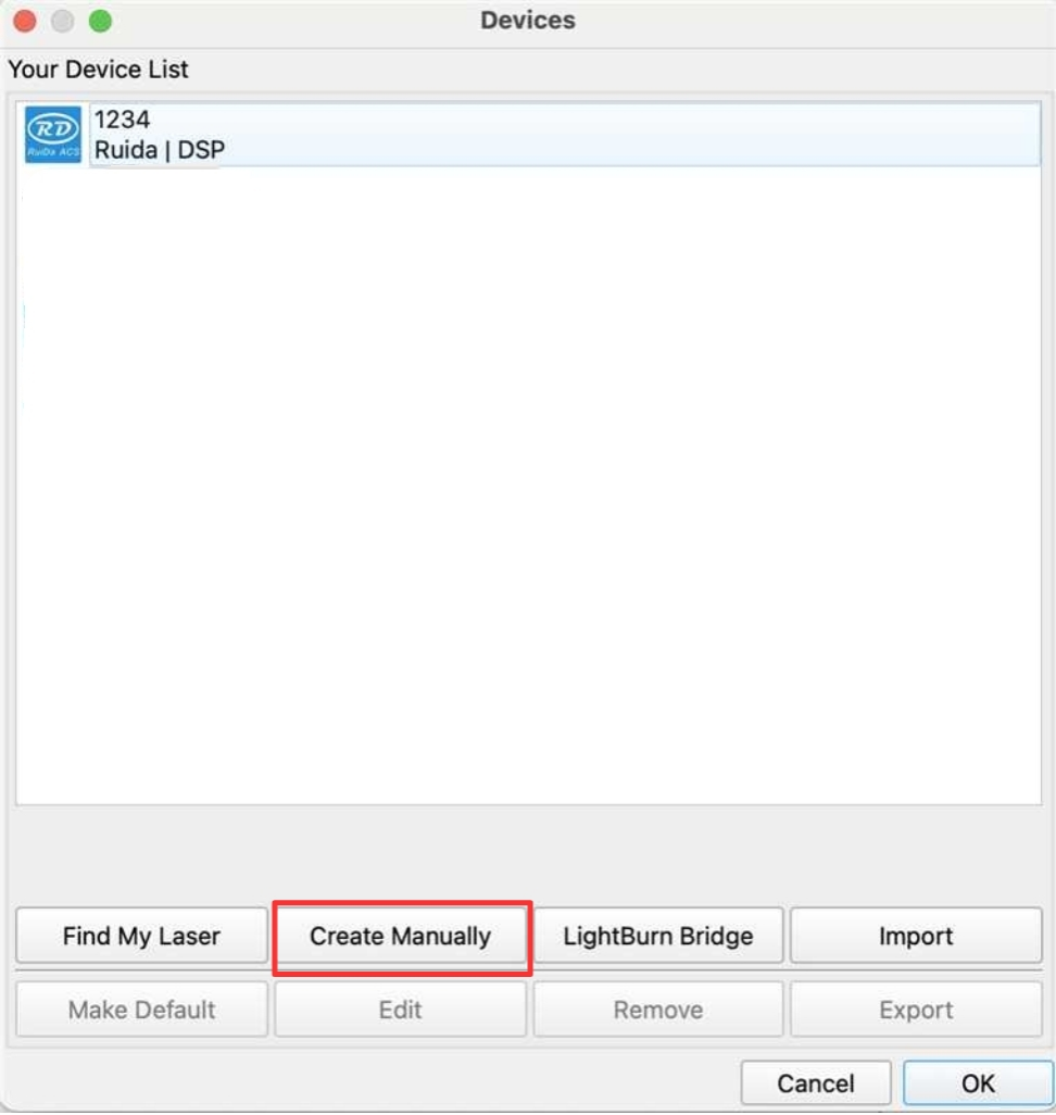
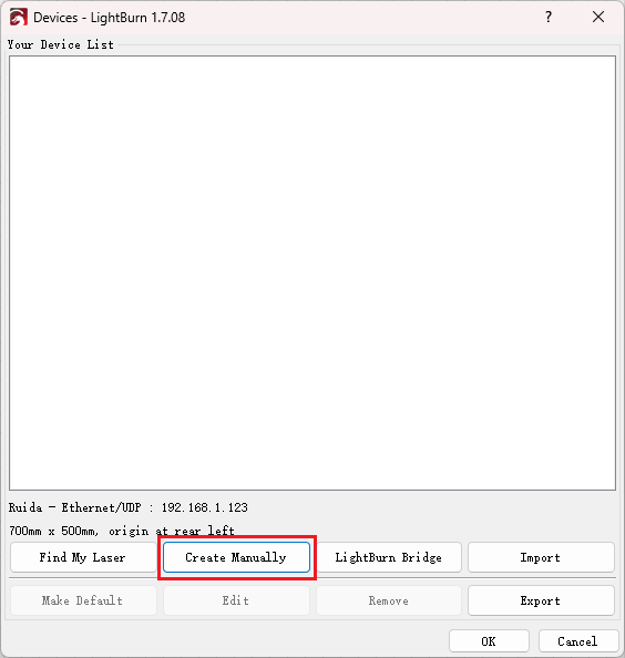
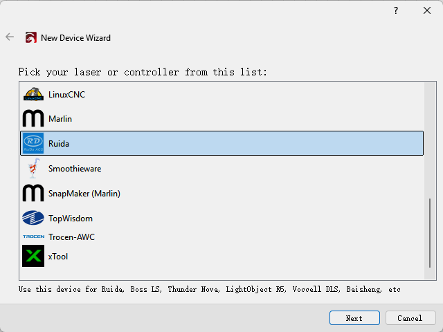
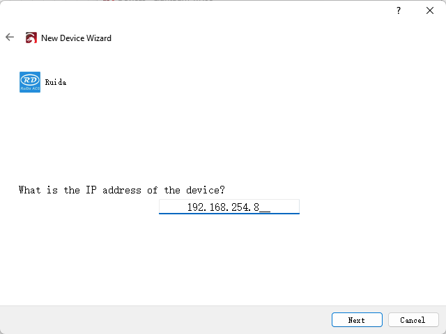
Click "Devices" from right bottom corner of the software. Click "Create Manually" to set up by the Devices setting.
Mac:
Win:
Then follow instructions to complete the connection steps step by step.
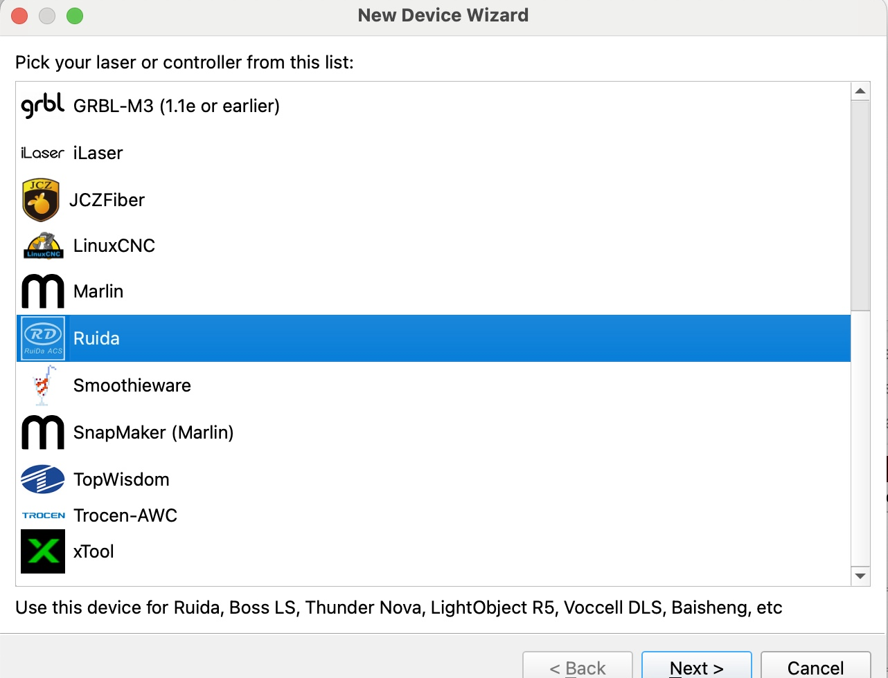
Critical: Under Controller Type dropdown, MUST select "Ruida". The entered IP MUST exactly match the VertiGo's configured address.
Mac:
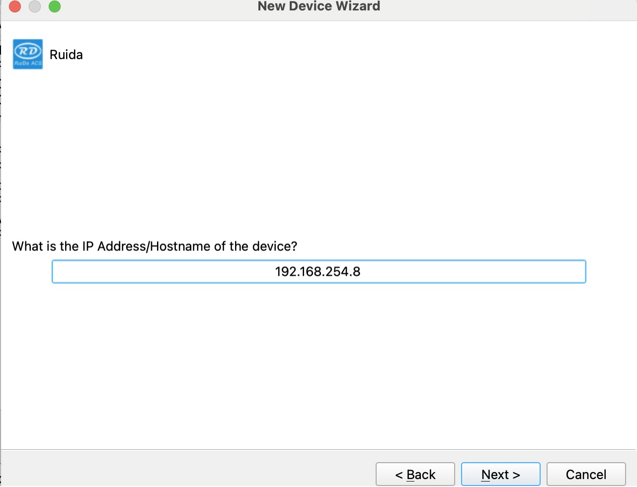
Win:
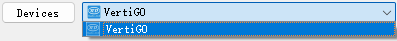
After successful device creation, locate and select the newly created "VertiGO" entry in the bottom-right panel (Device List section).
WIFI Connection
The system supports two WiFi modes: Hotspot Mode and Repeater Mode.
1. Hotspot Mode
Connect your computer directly to the VertiGo's built-in router:
- SSID Format: [Machine Model]_Hotspot_[Last 5 digits of S/N]
(Example: HYDRA70_Hotspot_8A2B4)
- Default Password: 12345678
The hotspot's default IP subnet is 192.168.254.xxx. Set VertiGo's IP address within 192.168.254.xxx. Important: The last octet of the hotspot's IP must differ from VertiGo's IP address.
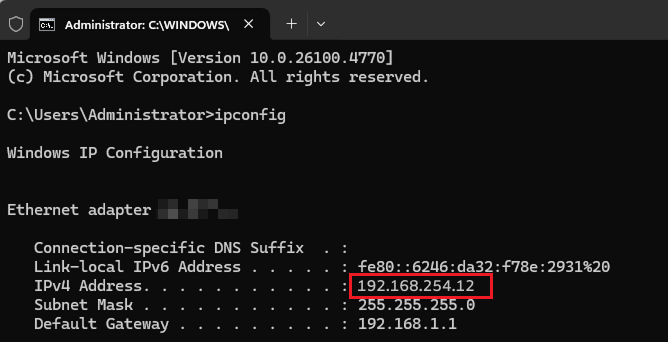
To verify the hotspot subnet on your computer:
①Windows: Open Command Prompt, type "ipconfig", and check the IPv4 address.
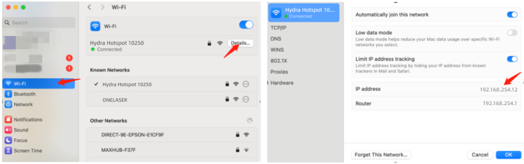
②Open WiFi settings, view network details, and locate "IP address".
How to Viewing/Modifying VertiGO IP Address?
2. Repeater Mode
Users can bridge the VertiGo's WiFi module to their primary router network. This allows both the VertiGo and computer to connect remotely via the user's regular WiFi.
Setup Procedure:
1.Connect your computer to the VertiGo's hotspot:
- SSID: [Machine Model]_Hotspot_[Last 5 S/N digits]
- Password: 12345678
2.Open a web browser and enter: 192.168.254.254 or http://vonets.cfg


3.Log in to the bridge device console:
- Username: admin
- Password: admin
- Click "Login"
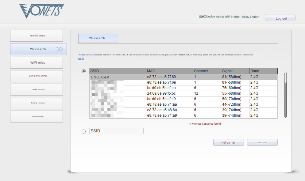
4.Configure bridging:
- Click "WIFI Search"
- Select your target WiFi network
- Click "Next"
5.Enter the target WiFi's password. Check and disable hotspot. Do not modify advanced/other settings.
6.Click "Submit".

The device supports Wi-Fi 4 (802.11n) / Wi-Fi 5 (802.11ac) protocols. When bridging, the upstream router must not exceed Wi-Fi 5 standards (i.e., cannot use Wi-Fi 6/6E or Wi-Fi 7).
To verify the hotspot subnet on your computer:
①Windows: Open Command Prompt, type "ipconfig", and check the IPv4 address.
②Open WiFi settings, view network details, and locate "IP address".
To establish communication between the PC and machine via the above methods, follow these steps:
MakerBoost
Click "Switch" from right bottom corner of the software, then click "Create" to set up by the Devices setting.
Mac:
Win:
Then follow instructions to complete the connection steps step by step.
Critical: The entered IP MUST exactly match the VertiGo's configured address.
Mac:
Win:
After successful device creation, select the newly created "VertiGo" entry in the machine list. Then click the "Connect" button. The software will instantly activate the connection.
For the detailed user manual of MakerBoost software, contact ONELASER Support to obtain the documentation.
Lightburn
Click "Devices" from right bottom corner of the software. Click "Create Manually" to set up by the Devices setting.
Mac:
Win:
Then follow instructions to complete the connection steps step by step. Critical: Under Controller Type dropdown, MUST select "Ruida". The entered IP MUST exactly match the VertiGo's configured address.
Mac:
Win:
After successful device creation, locate and select the newly created "VertiGo" entry in the bottom-right panel (Device List section).
¶ 4.4 How to Use the Display
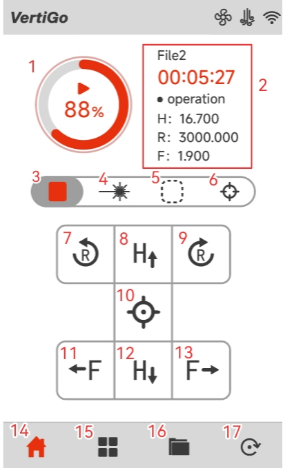
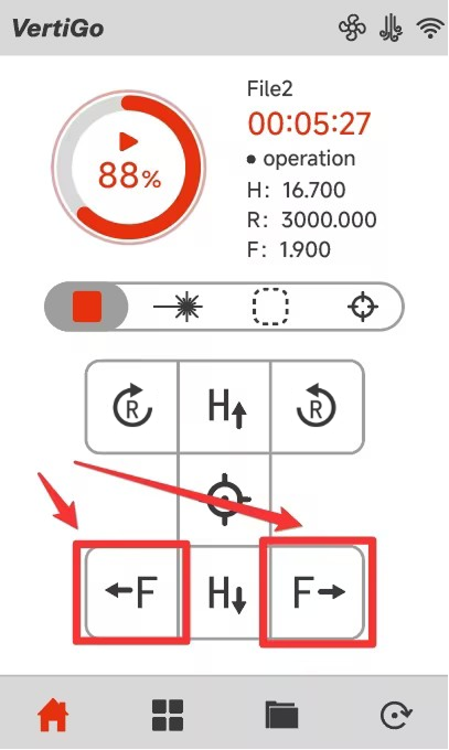
Main Interface
|
1. Start / Pause the job |
2. Display of working hours and coordinates of X, Y and Z axes |
|
3. Stop the job |
4. Pulse button |
|
5. Frame button |
6. Autofocus button |
|
7. The fixture rotates counterclockwise |
8. The laser head moves to the top in the X-axis (H-axis) direction |
|
9. The fixture rotates clockwise |
10. Origin button |
|
11. The fixture moves to the left in the Z-axis (F-axis) direction |
12. The laser head moves to the bottom in the X-axis (H-axis) direction |
|
13. The fixture moves to the right in the Z-axis (F-axis) direction |
14. Main interface |
|
15. Menu interface |
16. Memory interface |
|
17. Reset button |
|
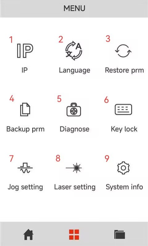
Menu Interface
|
1. Enter the IP address setting interface |
2. Enter the switch language interface |
|
3. Restore factory parameters |
4. Backup current parameters |
|
5. Enter the Diagnostics interface |
6. Keyboard lock to prevent being touched by mis-take |
|
7. Enter the laser head movement settings interface |
8. Enter the pulse settings interface |
|
9. System version information interface |
|
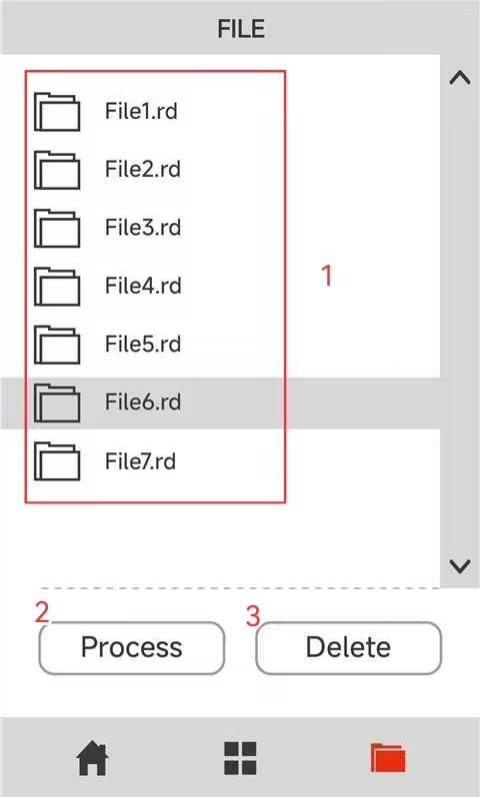
Memory Interface
|
1. The list stores the files that have been transmitted to the various devices |
2. Click on “Process” to process the selected files |
|
3. Click “Delete” to delete the selected files |
|
¶ 4.5 How to Use the Auto-focus and the Manual Focus Function
¶ 4.5.1 Auto-focus Function
The fixture is capable of moving left and right. It will carry the material towards the laser head, making contact with the focusing accessory. Subsequently, it will be adjusted to the appropriate focal length to ensure that an optimal distance is maintained between the material and the laser head. By using the auto focus function, users can focus quickly and accurately before cutting and engraving which saves the time of cutting and engraving and brings the better cutting engraving result.
The diameter range of the processing materials for VertiGo's auto-focus is 89~230mm (3.5”~9.05”).
Please follow the steps below to use the Auto focus function:
Secure the workpiece on the fixture → Click AF button on panel.
After that, the needed focus will be set automatically.
Important: Ensure you press the auto-focus button only once per auto-focus operation.

When using the autofocus function, be careful to avoid the workpiece hitting the laser head, otherwise you will damage the machine and the laser head!
¶ 4.5.2 Manual Focus Function
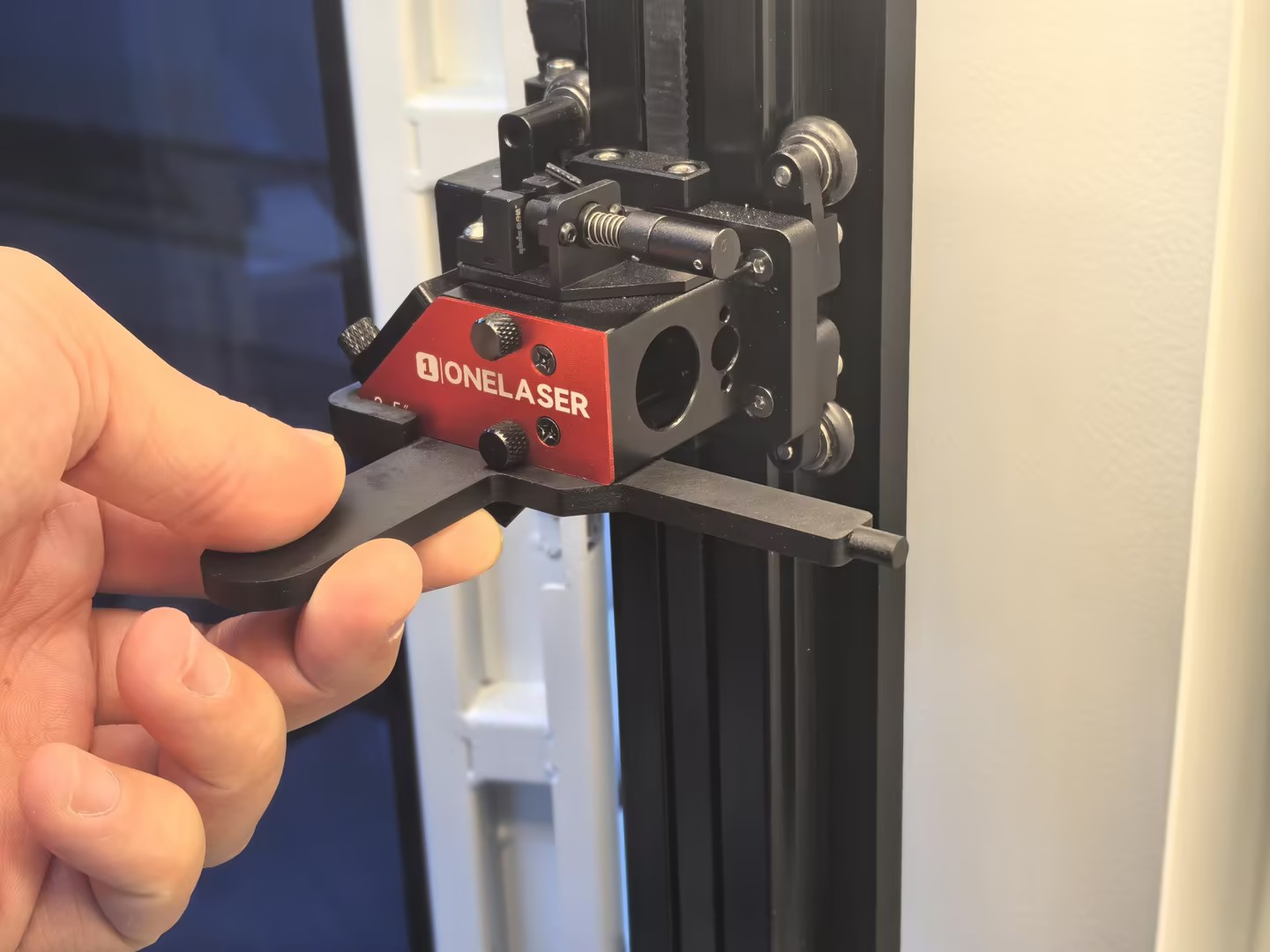
¶ Case 1: Workpiece Diameter Smaller Than the Auto-Focus Minimum
If the diameter of the workpiece to be processed (15–89 mm) is smaller than the minimum diameter supported by the auto-focus system (89 mm), manual focusing is required.
1.Secure the workpiece in the fixture, ensuring it is level and stable.
2.Insert the manual focusing tool along the lower surface of the laser head and align it with the edge protrusion.
3.Adjust the workpiece along the F-axis until it just touches the manual focusing tool.
Note: Use the on-screen controls to move the workpiece left or right along the F-axis.
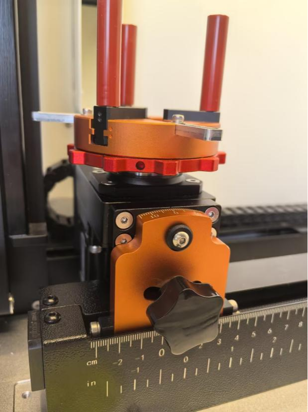
¶ Case 2: Workpiece Diameter Larger Than the Auto-Focus Maximum
If the diameter of the workpiece (230~300mm) to be processed exceeds the maximum diameter (230mm) supported by the auto-focus system, but the diameter at the clamping position remains within the allowable range of the chuck (20~230mm), manual focusing is required.
1.Secure the workpiece on the fixture, ensuring it is level and stable.
2.Note: The adjustment distance corresponds to the radius of the workpiece.
3.Use the on-screen controls to move the workpiece to the right along the F-axis until the distance between the 0° mark on the VertiGo angle marking plate and the 0 cm mark on the bottom F-axis equals the radius of the workpiece.
When using the manual focus function, be careful to avoid the workpiece hitting the laser head, otherwise you will damage the machine and the laser head!
¶ 4.6 The First Time Running the Laser
To be safe, never ever run the laser system unattended.
The following steps describe how to successfully engrave a first pattern. Prepare the device first:
1.Switch on the laser, then wait for the machine is initialized, and the laser head will do the reset and find the home from top left corner.
2. After machine finish resetting, place the workpiece on the working table, move the working table close to the laser head.
①Adjust the height of laser head.
②Run auto focus.
3.Connect the machine with an USB cable or Ethernet cable or WIFI.
¶ 4.6.1 Engraving test
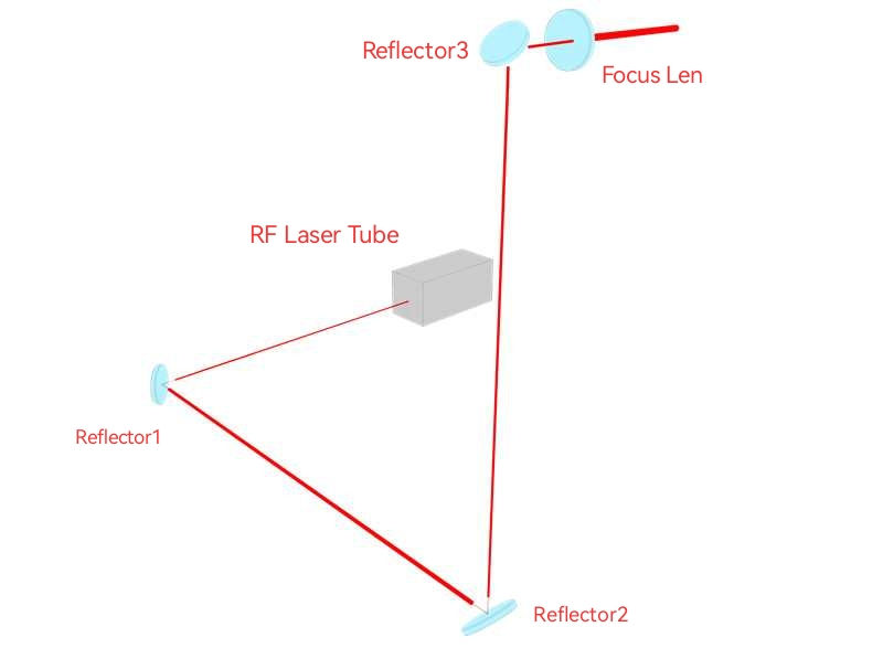
Before leaving the factory, each device undergoes professional calibration to ensure optimal performance. However, during transportation or relocation, pre-aligned components may shift slightly, affecting processing quality. Therefore, users should check the beam path and perform an engraving test before the first formal use.
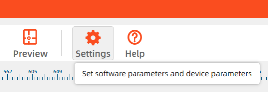
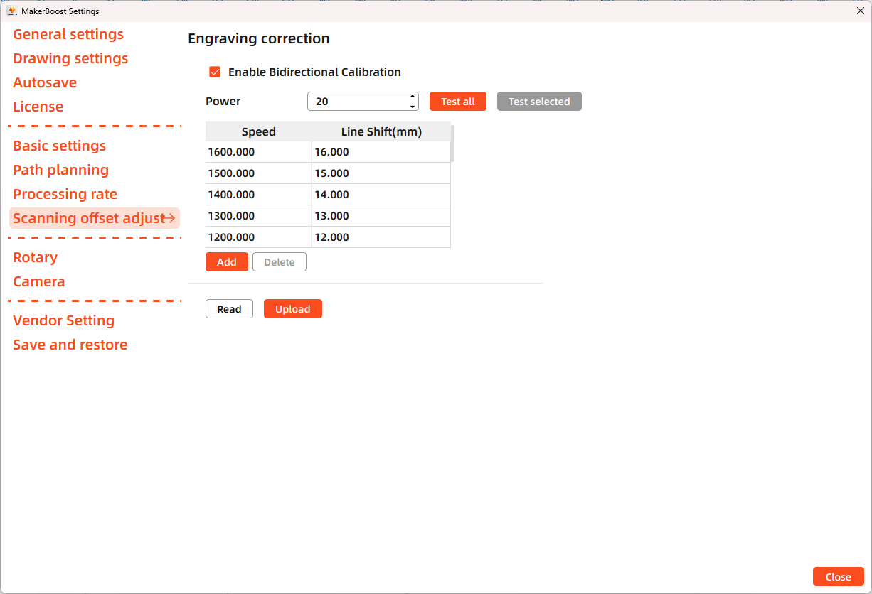
MakerBoost
Open MakerBoost software. Click "Settings" in the top toolbar, then select "Scanning offset adjust" in the dialog window. The software will read existing parameters from the device. Click "Test all" to get results. If misaligned lines appear, measure the distance between both ends of the line at that speed and adjust the "Line Shift" parameter.
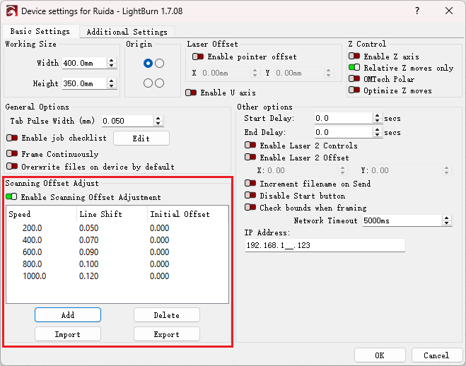
Lightburn
Open Lightburn software. Go to Devices Settings - Enable Scanning Offset Adjustment. Notice: Lightburn cannot read existing device parameters; users must manually enter values.
The particular values are showing with a picture in folder of laser software on the USB flash drive and on the Anodized aluminum piece that came with your machine.
¶ 4.6.2 Formal Engraving
After completing tests, you may formally operate the VertiGO. Create any text, graphics, or images using MakerBoost or Lightburn. Then set up the parameter and download the file to your machine.
- Control arrow button to move the laser head;
- Click "Origin" button to select the start point;
- Click "Frame" button on the display, please make sure that the material is in the right location and there is enough space for working.
- Finally press the "Start" button in the display, to start the engraving process.
When the engraving is complete, the laser machine will give out the notification sound and the laser head will go back to the original point, and the warning light will return to the green light, then you can repeat engraving. Please make sure the unit is in mm instead of inch.
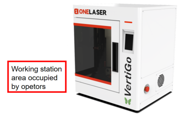
¶ 4.7 Workstation Area Indication
¶ 4.8 For Laser Engraving
The engraving depth can easily be varied through the laser power or the speed. To increase the engraving depth, reduce the speed or increase the power setting. This way you increase the amount of energy per area unit. Engraving too deep, however, reduces the quality of the details. With coated materials the required power depends of the kind and thickness of the coating. With power set too high the individual lines become too thick and a sharp picture cannot be achieved. The resolution of the graphics should usually be at 500 dpi. The dpi setting (number of laser dots per inch) depends on the material. The lower this setting is, the lower the resolution of the engraved picture will be. This, however, reduces flaming and increases the energy of a pulse, which can improve the overall result (e.g. when engraving some sorts of plastic materials).
1.Plastics
Plastics for engraving are available in many different colors and thicknesses and with many different coatings and surfaces. The majority of available plastics can be well engraved and cut with the laser. Plastics with a micro-porous surface seem to give the best result, because less surface material needs to be removed. As most plastic materials have a low melting point, a low pip setting should be selected to reduce the danger of melting.
2.Engrave the stainless steel
The various mixtures and densities of stainless steel cause a slightly varying engraving depth. Since engraving a stainless steel material requires a relatively high laser power, the laser power is principally set to suitable power and find out the correct speed setting.