¶ RF Tube Fails to Fire (No Laser Output) - X Series
This page provides a structured troubleshooting guide for situations where the RF tube does not fire despite the machine operating normally. It explains common causes, diagnostic steps, and corrective actions to help identify whether the issue is related to optics, power, wiring, control boards, or RF tube lifespan.
¶ Problem Description
When the machine is operating and the laser head moves and the fans spin are normal. However, the RF tube does not fire (there is no laser output) because no mark is left on the material.
¶ Cause
- Layers: The power settings for the layers in the design file are too low.
- Optics: The beam path is misaligned. The machine has not been maintained on schedule, causing the optics (mirrors/lenses) to be unable to transmit or reflect light, leading to complete damage.
- Pre-ignition: The machine remains in the pre-ignition state after startup, and the three characteristic "beeps" are not heard.
- Power: The power supply is damaged.
- Wiring: The connecting wires or plugs are loose or damaged.
- Control Board: The fan control board port is damaged.
- Tube Life: The RF tube has suffered natural aging (after a very long period of use) or is damaged.
¶ Solution
Important Reminder:
It is normal for the XRF model not to fire for the first few seconds immediately after turning it on. The internal components require preparation time, and the machine is considered ready only after you hear three beeps from the buzzer.
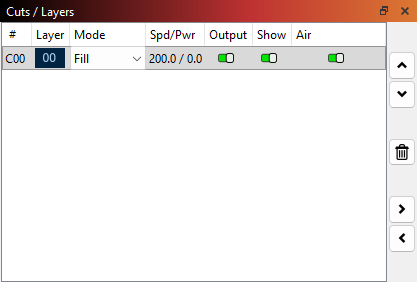
¶ Method 1. Check Layer Parameters
Check if the power setting for one or more layers is too low, causing the machine to appear as if it's not emitting laser.
¶ Method 2. Confirm Ambient Temperature
The operating environment temperature for the laser tube must be between 41°F and 104°F (5°C and 40°C). Operating outside of this temperature range may lead to abnormalities, such as the laser tube failing to fire (no laser output).
¶ Method 3. Check for Output Directly at the RF Tube
Remove the back cover of the XRF machine. Place a piece of wood in front of the RF tube exit aperture. Click the Pulse button on the control panel to check if the laser is firing from the RF tube exit.
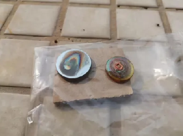
¶ Method 4. Check for Lenses and Beam Path Misalignment
Inspect the mirrors, beam combiner, and focus lens along the beam path.
Beam Path Misalignment and Adjustment Tutorial Link: Beam Path Misalignment
¶ Method 5. Check the Pre-ignition Status
After powering on, the RF tube undergoes a pre-ignition process that takes approximately 45 seconds. You must wait until you hear three "beep" sounds, which indicate the RF tube is ready to fire.
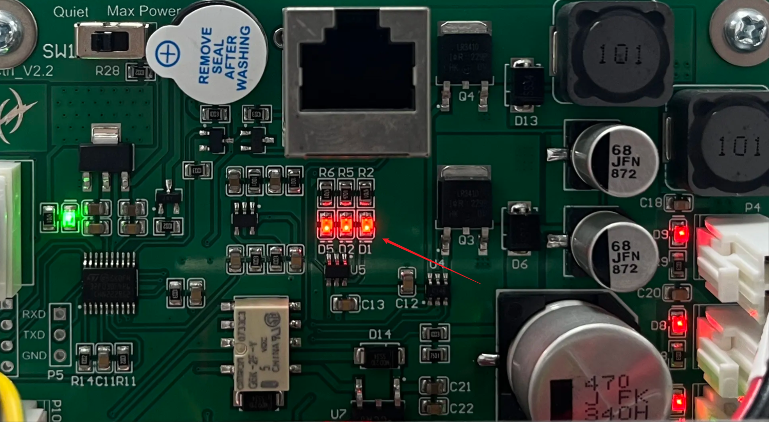
If you do not hear the beeps after 45 seconds, open the machine's back cover and inspect the D5, D2, and D1 indicator lights on the board.
- Normal State: D5, D2, and D1 should be OFF.
- Abnormal State: If they remain ON (solid), refer to the following:
- D5 (Solid): Indicates a voltage issue. Please follow the electrical troubleshooting steps.
- D2 (Solid): Indicates the RF tube temperature is too high. The laser will not fire. Stop all operations and wait 4–5 minutes for the tube to cool down before retrying.
- D1 (Solid): Indicates the device is still in the pre-ignition phase. Wait a few more minutes.
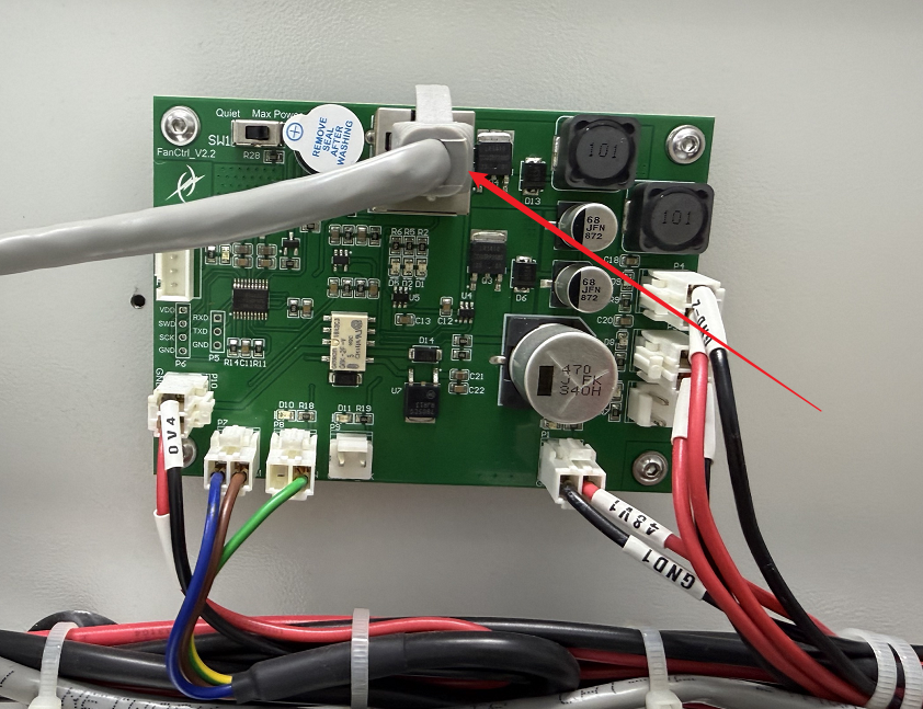
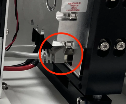
If the lights do not turn off, locate the grey network cable. Unplug and replug both ends (at the FanCtrl board and the RF tube). If the issue persists, replace it with a known working network cable.
¶ Method 6. Check the Power Supply
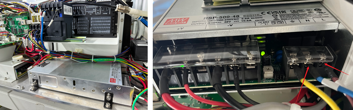
Prepare a multimeter. Locate the power supply and check if the green indicator light is steadily lit:
- If the green light is steadily lit: Use the probes to measure whether the voltage between +V and -V is 48V. If the voltage is abnormal, it indicates a power supply failure.
- If the green light is NOT lit: Use the probes to measure whether the voltage between L2 and N2 is 220V. If the voltage is normal, it indicates a power supply failure. If the voltage is abnormal, it indicates a wiring issue.
¶ Method 7. Inspect Wiring and Connections
Remove the right side and back covers of the XRF machine and prepare a multimeter.
On the right side of the XRF, locate the mainboard and find the CN11 PWM port. Set the multimeter to continuity mode. Use the probes to measure whether the PWM and GND ports of CN11 (the brown wire and the blue wire) have continuity.

Locate the FanCtrl board at the back of the XRF. Use the multimeter in continuity mode to measure whether the PWM and GND ports (the brown wire and the blue wire) have continuity and measure whether the yellow&green wire port and the GND port are reading 5V.
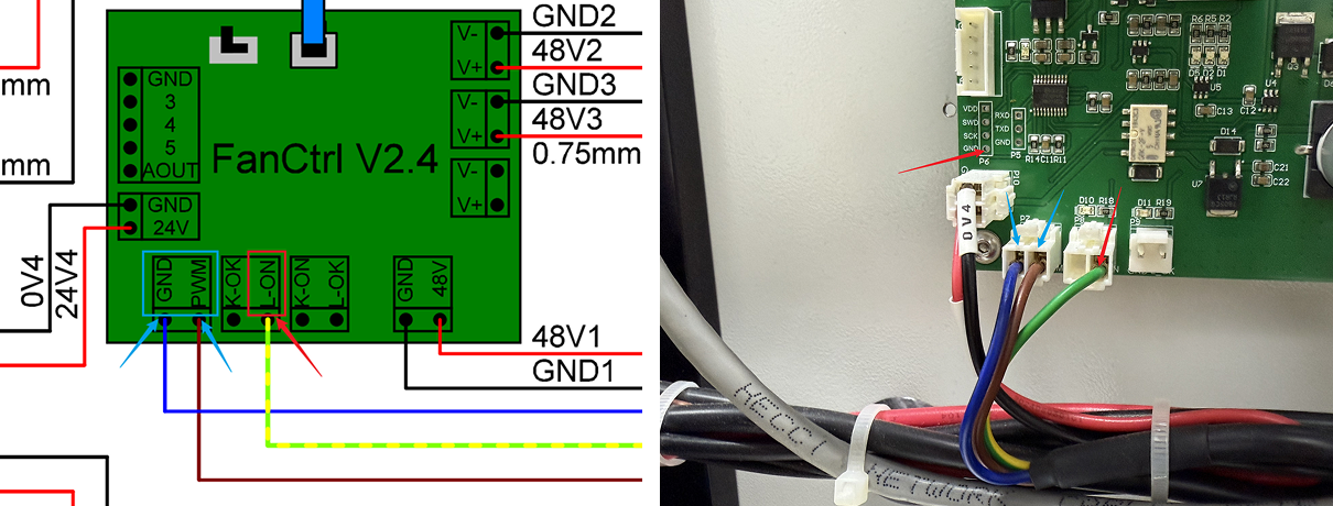
With the machine powered OFF, check if the wire on the upper part of the FanCtrl board are securely plugged in. Inspect the aforementioned wires to ensure they are firmly seated in their ports and that no wires are damaged.
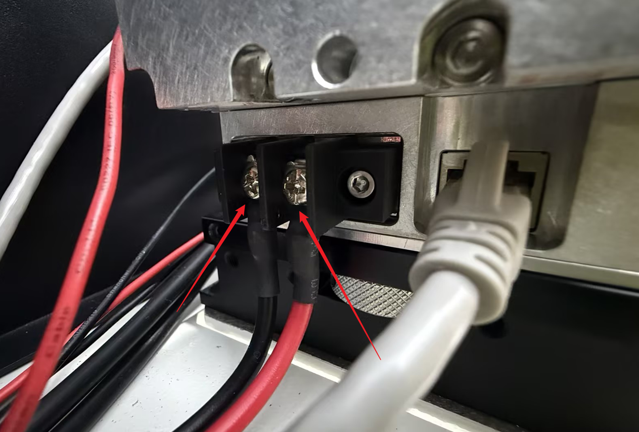
Check if the power supply wires (positive and negative terminals) of the RF tube are securely connected.
¶ Method 8. Test the RF Tube
To determine if the fault lies with the RF tube itself or the control signal, perform a short-circuit test using a standard network cable:
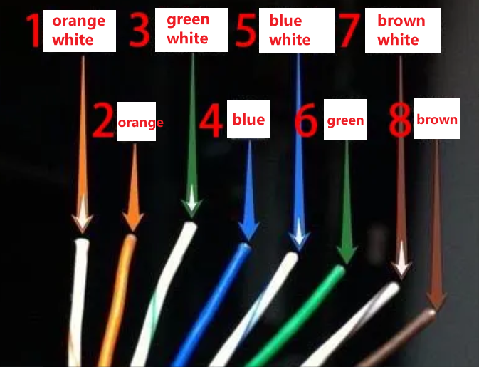
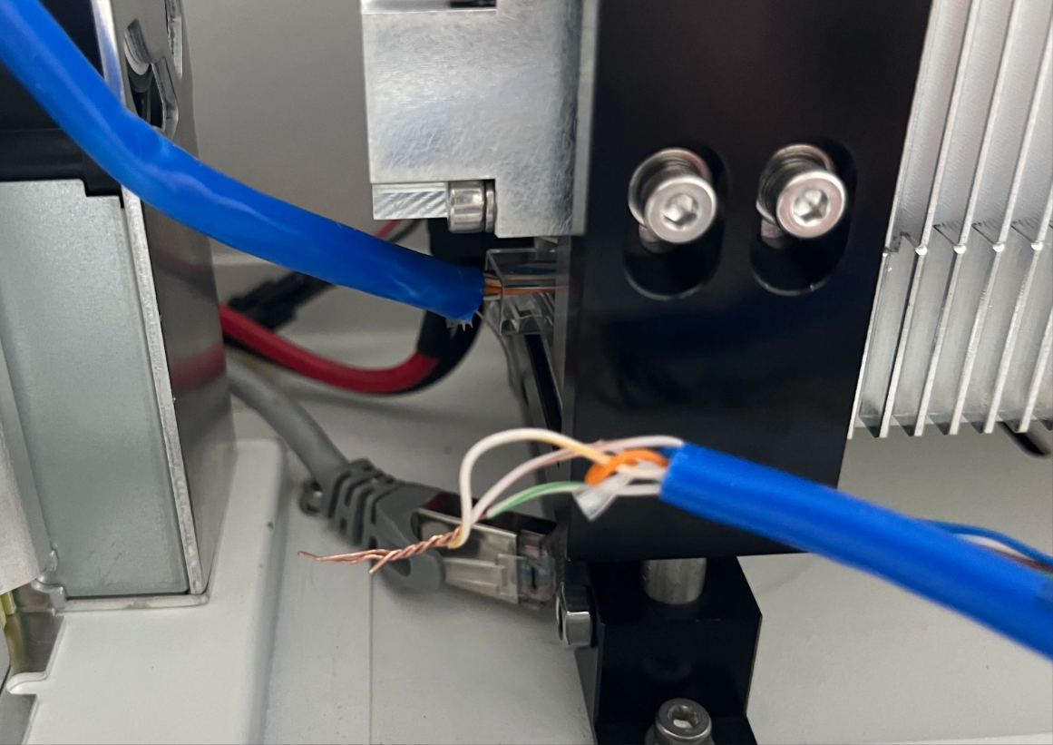
1. Take a working network cable and cut off the crystal head from one end.
2. Strip and short-circuit (twist together) wires 1, 3, and 7 (Orange-White, Green-White, and Brown-White).
Note: This end does not need to be plugged back into the motherboard.
3. Plug the other end of the cable into the network port on the RF tube.
4. Turn on the machine and wait 42 seconds for the pre-ignition period to finish.
- Laser Fires: The RF tube is functional. The problem lies with the control signal or motherboard.
- No Laser: The RF tube is faulty and needs to be replaced.
Safety Warning:
Place a piece of wood or scrap material on the workbed before turning on the machine, as the RF tube may fire continuously during this test.
Important Reminder:
If these steps do not resolve the issue, please submit a support ticket on ZOHO: https://zohodesk.1laser.com/portal/en/newticket. A technician will then be able to conduct a more in-depth diagnosis and resolve your problem.