¶ Introduction
This manual offers comprehensive guidance on installing and operating the Air Assist Control kit. It is divided into four chapters:
1. Product Introduction
2. Installation on X Series
3. Installation on Hydra Series
4. Air Assist Operation Instructions
Critical Installation Notice
All accessory installations must comply with ONELASER technical specifications to ensure proper operation of the Air Assist Control system. Failure to comply will result in: performance degradation, reduced service life, increased maintenance costs and even permanent equipment damage.
Manual Usage Guidance
This manual outlines the technical installation standards. Be sure to read it completely before beginning operation. If you encounter any installation issues, contact technical support without delay.
¶ Contents
- Chapter 1. Product Introduction
- Chapter 2. Installation on X Series
- Chapter 3. Installation on Hydra Series
- Chapter 4. Air Assist Operation Instructions
¶ Chapter 1. Product Introduction
¶ 1.1 Introduction
The Air Assist Control is specifically designed for the ONELASER X / Hydra series. It provides enhanced air assist pressure control, enabling the machine to:
- Precisely control high/low air pressure by design layer, significantly enhancing cutting and engraving performance on diverse materials.
- Offer visual air pressure display for more intuitive operation.
- Facilitate convenient adjustment of high/low pressure settings to meet diverse processing needs.
¶ 1.2 Specifications
|
Name |
Parameter |
|
Dimensions (L×W×H) |
230×100×75 mm |
|
Weight |
Approx. 2.5 kg |
|
Gas Source Requirement |
Non-corrosive and non-flammable gas |
|
Max Input Pressure |
1.05 MPa / 152.28 psi |
|
Min Input Pressure |
0.5 MPa / 72.52 psi |
|
Operating Pressure Range |
0-0.7 MPa / 0-101.52 psi |
|
Operating Ambient Temp. |
±3%FS (0-50℃) |
|
Operating Ambient Humid. |
35%-85% RH |
|
Inlet/Outlet Port Size |
Ø 6 mm air hose |
* Due to pressure reduction as air enters the system, a 0.6 MPa supply may register as only 0.5 MPa on the digital pressure gauge. This pressure drop is considered normal if it falls within the expected range.
¶ Chapter 2. Installation on X Series
¶ 2.1 Component List in Air Assist Control Box
|
Number |
Name |
|
A |
Control Cable 1 (DB9 Female) |
|
B |
Control Extension Cable 2: Hydra-Series Only (5-Wire Port) |
|
C |
Air Filter Regulator |
|
D |
Cable Ties / Cable Tie Mounts / Adhesive Hook / 6mm to 6mm Adapter |
|
E |
Relays |
|
F |
Air Hose (2.8m) |
|
G |
Air Assist Kit |
¶ 2.2 Pneumatic Installation Instructions
¶ 2.2.1 Gas Source Requirements
A dry, clean gas source must be used, with an operating pressure range between 0-0.7 MPa. Strictly control the water and oil content in the compressed air. Failure to do so may clog the nozzle, contaminate optical lenses, and in severe cases, may cause a fire.
¶ 2.2.2 Connection Steps
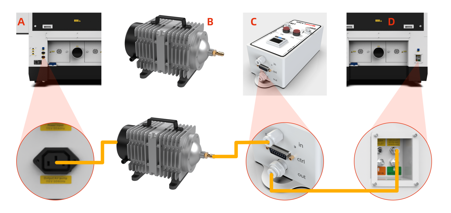
Using the Built-in Air Pump:
X-series devices come equipped with a built-in air pump. No installation is required by the user.
Note: The original air pump delivers lower output pressure, making it suitable for limited scenarios (e.g., thin sheet cutting). For processing a wider range of materials, using an external air compressor system is recommended for significantly improved processing results. Optimized gas source solutions and test data will be continuously updated on the official website. Stay tuned for updates.
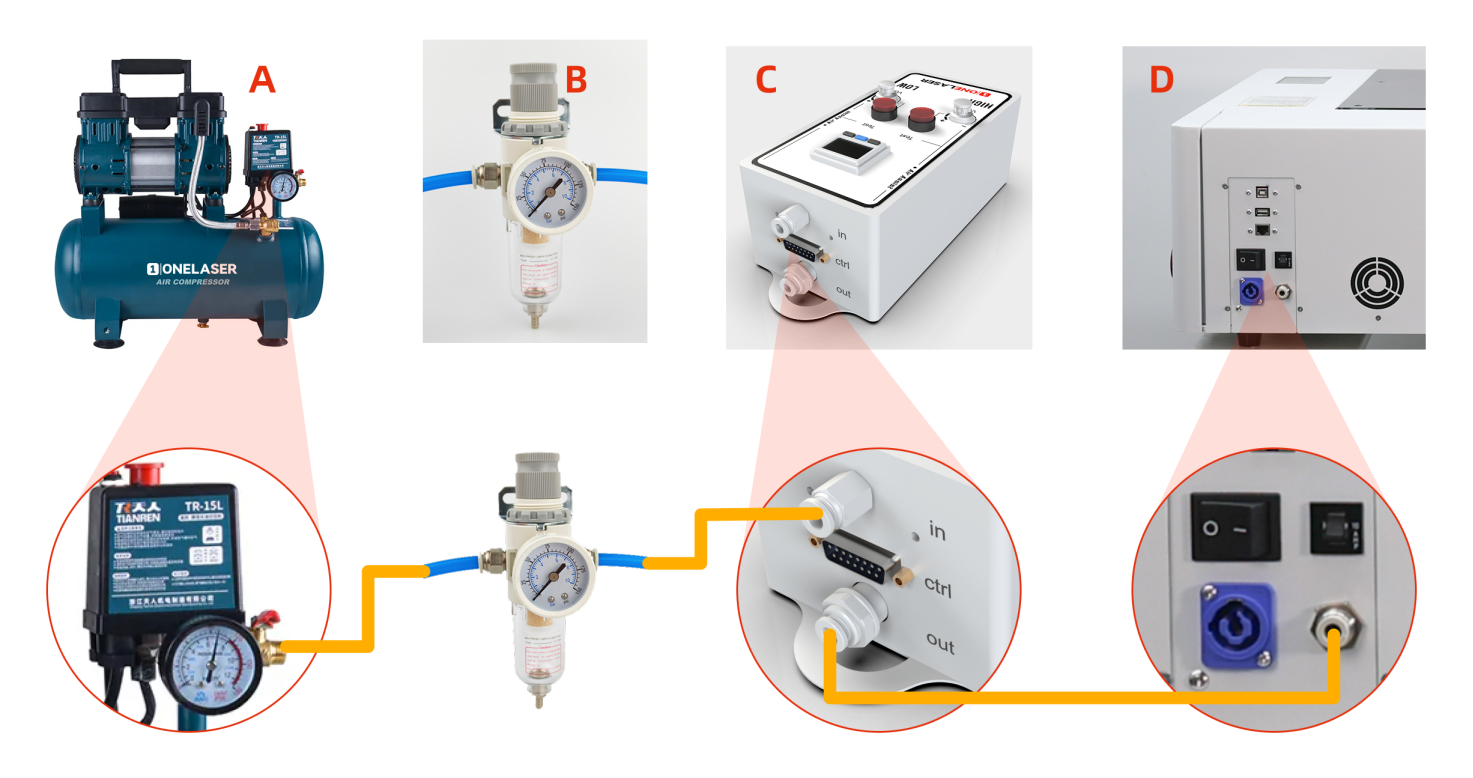
Connecting an External Air Compressor:
Before connecting, power off the device and disconnect the Power Input located on the lower back of the device.
- Connect the Air Compressor (A) to the Air Filter Regulator (B): Connect the air hose from the air compressor's OUTLET to the IN (Inlet) port of the Air filter regulator.
- Connect the Air Filter Regulator (B) to the Air Assist Kit (C): Connect the air hose from the OUT (Outlet) port of the Air filter regulator to the IN (Inlet) port of the air assist kit.
- Connect the Air Assist Kit (C) to the Device (D): Connect the air hose from the OUT (Outlet) port of the air assist kit to the Gas Source Input Port on the back of the device.
Important:
If you are using the XT device, these steps requires transforming the internal connections:
- Remove the rear cover, then remove the right-side cover of the device.
- Disconnect the internal connector found inside the right-side cover area before proceeding (failure to disconnect may cause wiring damage).
- Locate the 6 mm to 6mm adapter. Disconnect the air hose from the compressor side.
- Find the air hose connected internally to the device's external gas inlet port. Insert the free end of this hose into the 6mm to 6mm adapter.
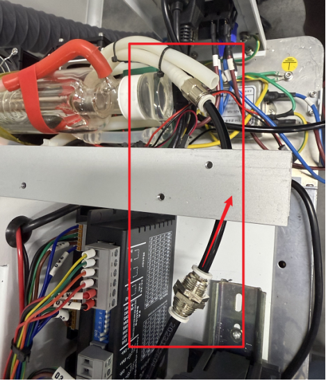
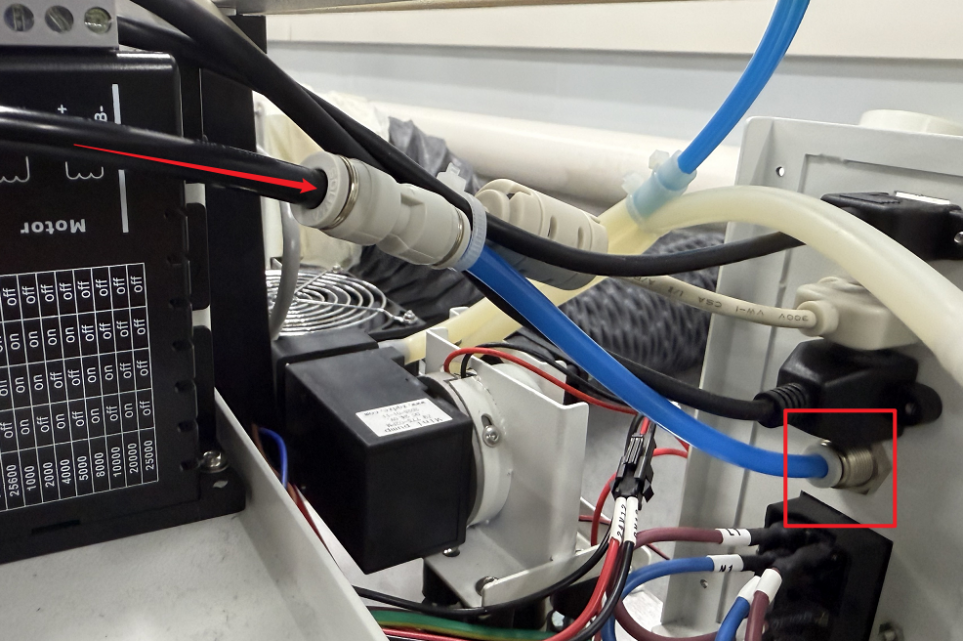
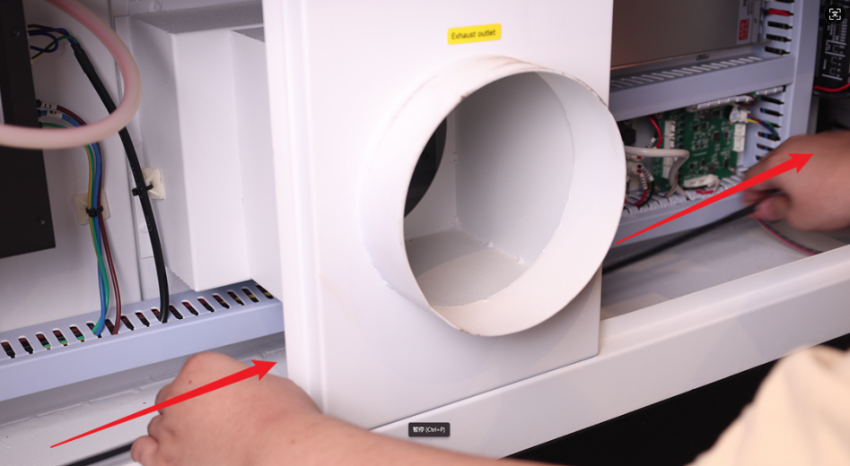
If you are using the XRF device, these steps requires transforming the internal connections:
- Remove the rear cover, then remove the right-side cover of the device.
- Disconnect the internal connector found inside the right-side cover area before proceeding (failure to disconnect may cause wiring damage).
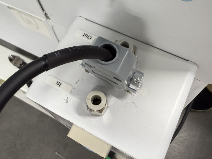
- Locate the connected air hose as shown in the figure below. Disconnect the white air hose while keeping its adapter attached.
- Find the blue air hose connected internally to the device's external gas inlet port. Insert the black air hose into the 6mm to 6mm adapter.
- Inspection & Confirmation: Ensure all connections are securely fastened without looseness. The air compressor must be powered by an external power source.
¶ 2.3 Electrical Circuit Installation Instructions
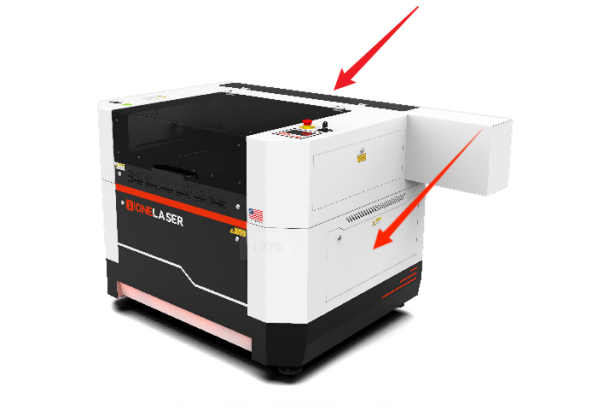
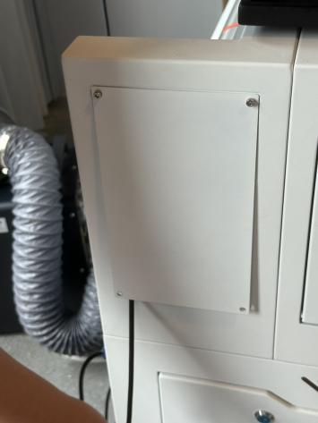
- Remove the Covers: Power off the device and disconnect the "Power Input" located on the lower back of the device before starting any electrical connections. Remove the rear cover of the machine. Then, remove the right-side cover.

Important: Disconnect the internal connector located inside the area of the right-side cover before removing the cover. Failure to disconnect it first may cause wiring damage.
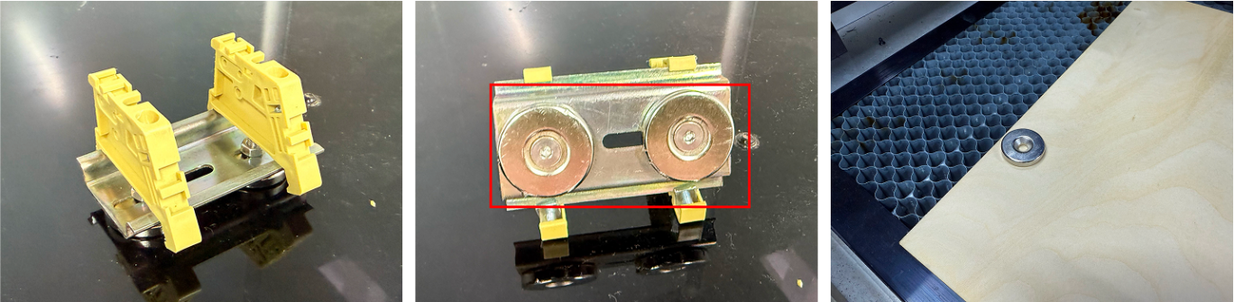
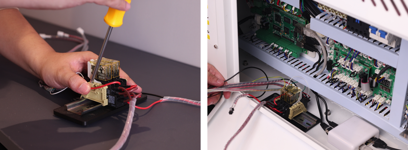
- Install the Relay: Locate the relay component from the Air Assist Control Box. Remove the base and mounting hardware from the air assist kit relay, then detach the existing mounting hardware from the equipment relay. Remount both relays on the DIN rail to complete the installation.
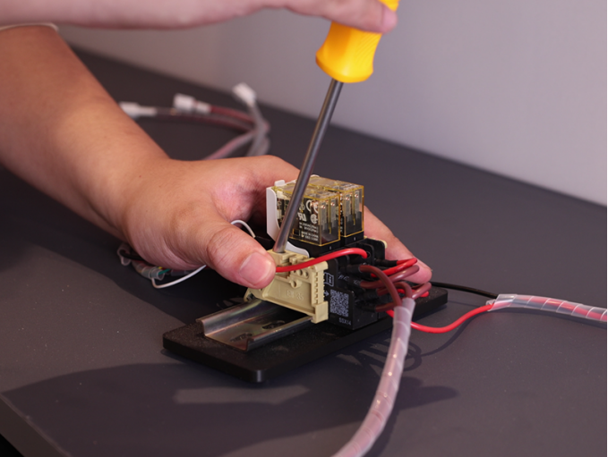
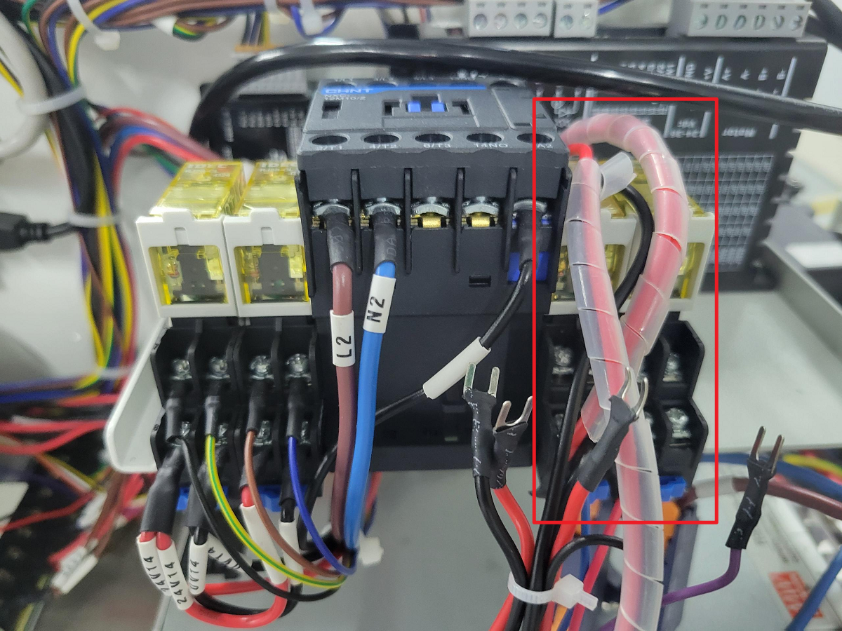
Note: The magnet on the base is removable and can be reused (if needed) for securing materials.
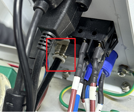
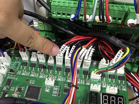
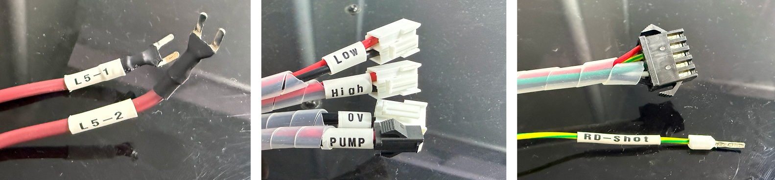
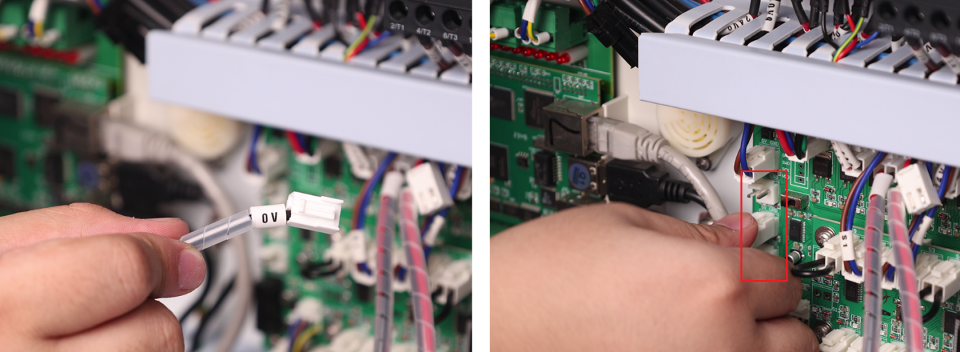
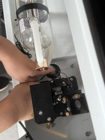
- Locate Components: Find the TL Mainboard (refer to the diagram). Identify the relay cable labels from the Air Assist Control Box: 0V, LOW, HIGH, PUMP, L5-1, L5-2, RD-Shot.
- Connect Control Wires:
- 0V → Connect to any 5V GND terminal on the left side of the TL Mainboard (choose 1 of the 3 terminals marked for 5V GND).
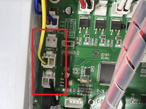
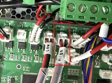
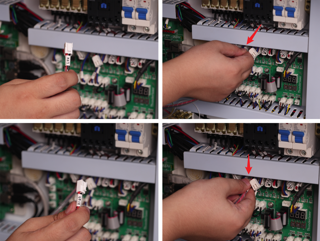
2. LOW → Connect to the OUT 4 24V GND terminal on the TL Mainboard (locate the OUT4 marking on the board).

3. HIGH → First, disconnect the plugs currently connected to the OUT 5 24V GND terminal on the TL Mainboard (locate the OUT5 marking). These plugs are typically labeled 0V 12 and 24V 12. Then, connect the "HIGH" control wire to this now vacant OUT 5 24V GND terminal.
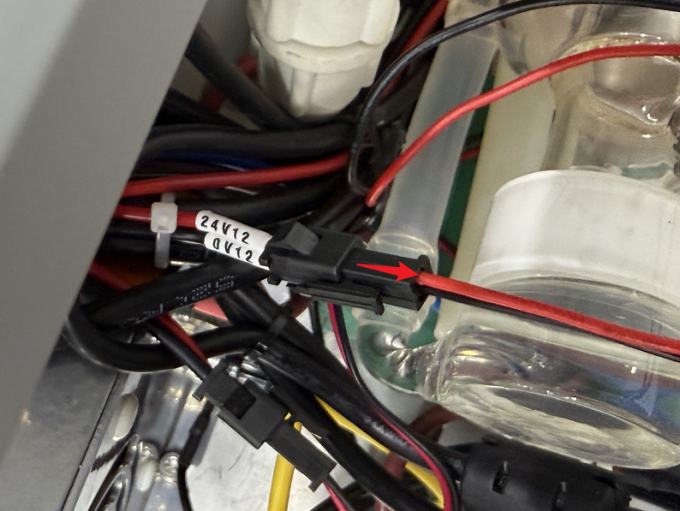
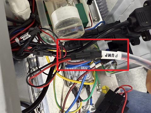
- Reconnect Pump Power:
1. Locate the 24V 12 and 0V 12 terminal pairs on the back of the machine.
2. First, disconnect the original plug(s) from these terminals.
3. Then, connect the PUMP wire to the air pump terminal.
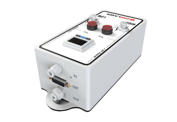
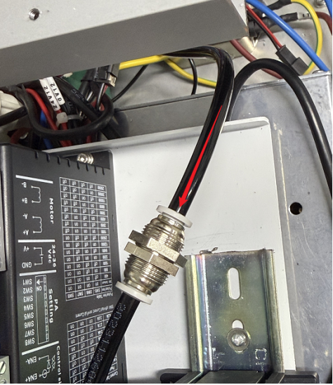
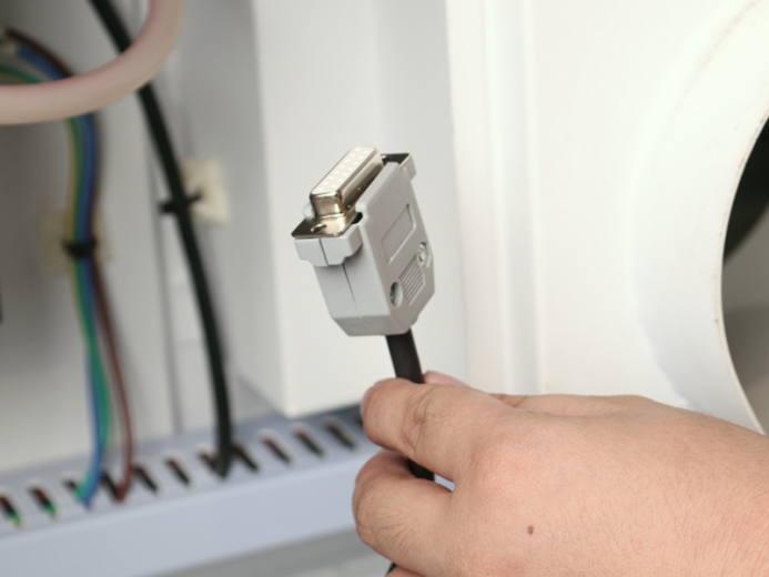
- Connect the Ctrl Interface:
1. Find the Control Cable1(DB9 Female) with the plug shown in the diagram below.
2. Connect the socket end of this cable (opposite the diagrammed plug) to the 5-wire port on the relay.
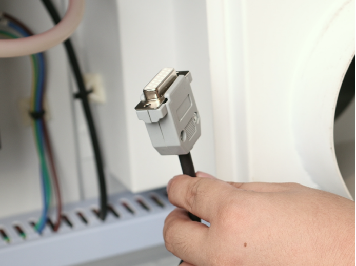
3. Reattach the side cover, ensuring the cable passes through a suitable opening/grommet.
4. Plug the DB9 Female into the port labeled Ctrl on the device to complete the circuit connection.

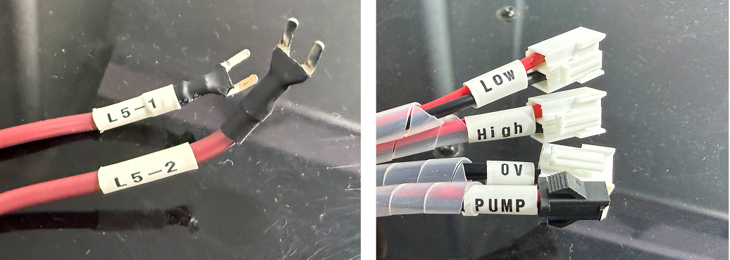
- Unused Wire Handling: The RD-Shot, L5-1 and L5-2 cables do not require connection. Securely bundle and stow these unused wires away from moving parts or connectors.
¶ Chapter 3. Installation on Hydra Series
¶ 3.1 Component List in Air Assist Control Box
|
Number |
Name |
|
A |
Control Cable 1 (DB9 Female) |
|
B |
Control Extension Cable 2: Hydra-Series Only (5-Wire Port) |
|
C |
Air Filter Regulator |
|
D |
Cable Ties / Cable Tie Mounts / Adhesive Hook / 6mm to 6mm Adapter |
|
E |
Relays |
|
F |
Air Hose (2.8m) |
|
G |
Air Assist Kit |
¶ 3.2 Pneumatic Installation Instructions
¶ 3.2.1 Gas Source Requirements
A dry, clean gas source must be used, with an operating pressure range between 0-0.7 MPa. Strictly control the water and oil content in the compressed air. Failure to do so may clog the nozzle, contaminate optical lenses, and in severe cases, may cause a fire.
¶ 3.2.2 Connection Steps
Using the Built-in Air Pump:
- Connect the Original Air Pump (B): Plug the connector end of the original air pump into the port labeled Output: Air pump located on the lower back (A) of the device. Connect the hose end of the original air pump to the "In" (Inlet) port of the Air Assist Kit (C).
- Connect the Air Assist Kit (C) to the Device: Connect a hose from the Out (Outlet) port of the Air Assist Kit (C) to the port labeled AIR ASSIST 55 PSI MAX / 400 kPa MAX located on the lower back (D) of the device.
Note: The original air pump delivers lower output pressure, making it suitable for limited scenarios (e.g., thin sheet cutting). For processing a wider range of materials, using an external air compressor system is recommended for significantly improved processing results. Optimized gas source solutions and test data will be continuously updated on the official website. Stay tuned for updates.
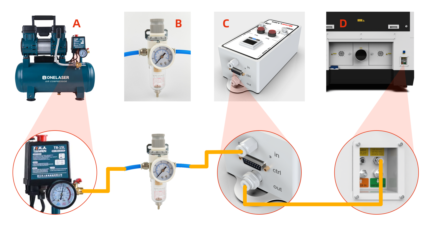
Connecting an External Air Compressor:
Power off the device and disconnect the Power Input located on the lower back of the device before starting any connections.
- Connect Air Compressor (A) to Air Filter Regulator (B): Connect the air hose from the OUTLET port of the Air Compressor (A) to the IN (Inlet) port of the Air Filter Regulator (B).
- Connect Air Filter Regulator (B) to Air Assist Kit (C): Connect the air hose from the OUT (Outlet) port of the Air Filter Regulator (B) to the IN (Inlet) port of the Air Assist Kit (C).
- Connect Air Assist Kit (C) to Device (D): Connect the air hose from the OUT (Outlet) port of the Air Assist Kit (C) to the Gas Source Input Port on the back of the Device (D).
- Verification & Power: Ensure all connections are secure and free from looseness. The air compressor must be powered by an external power source.
Important Note for External Air Compressor Setup:
When using an external air compressor, complete the following steps:
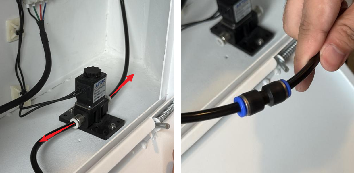
- Access the Regulating Valve: Open the access door/panel located on the lower-left side of the device. Locate the Regulating valve inside this compartment.
- Modify the Air Hose Connections: Disconnect both the inlet and outlet air hoses from the Regulating valve. Locate the 6mm to 6mm adapter in the accessories kit. Use this adapter to connect the inlet and outlet air hoses directly together (bypassing the Regulating valve).
¶ 3.3 Electrical Circuit Installation Instructions
- Access Panels: Power off the device and disconnect the Power Input on the lower back before starting any electrical work. Remove the right-side cover and rear cover (using the Hydra7 as an example).
- Install the Relay: Locate the relay component in the Air Assist Control Box. Install the relay base/mounting bracket. Secure the relay inside the right-side cover enclosure.
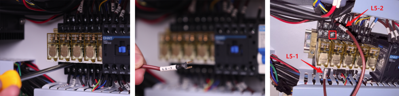
- Locate Components: Find the TL Mainboard. Identify the cable labels on the relay: 0V, LOW, HIGH, PUMP, L5-1, L5-2, RD-Shot.
- Connect Control Wires:
1. LOW → Connect to the OUT 4 24V GND terminal on the top row of the TL Mainboard (the 4th terminal from the left).
2. HIGH → Connect to the OUT 5 24V GND terminal on the top row of the TL Mainboard (the 5th terminal from the left).
3. 0V → Connect to any 5V GND terminal on the left side of the TL Mainboard (choose 1 of the 3 available terminals).
4. L5-1 → Connect to the lower row, 3rd terminal from the left of the device's Relay L5.
5. L5-2 → Connect to the upper row, 3rd terminal from the left of the device's Relay L5.
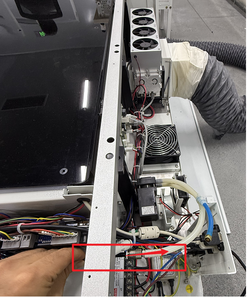
- Connect the Ctrl Interface:
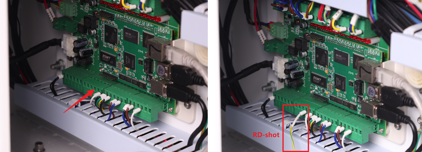
1. Locate the wire labeled RD-shot. Plug it into the 4th small terminal of the 2nd large terminal block located the bottom-left section of the TL Mainboard.
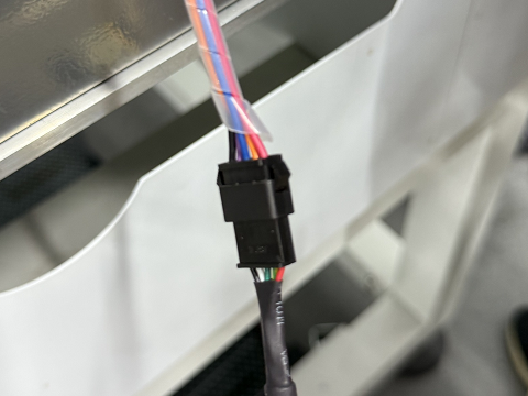
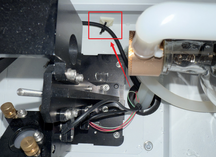
2. Locate Control Cable 1 (DB9 Female) and Control Cable 2 (5-Wire Port) inside the air assist control box. First, mate the two cables together to extend the overall length – we will refer to this combined cable as the "Assembled Cable". Then, connect the 5-Wire Port end of the Assembled Cable to the 5-Wire Port on the relay, as shown in the figure below.
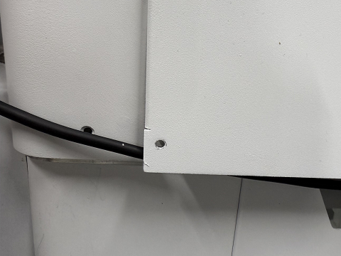
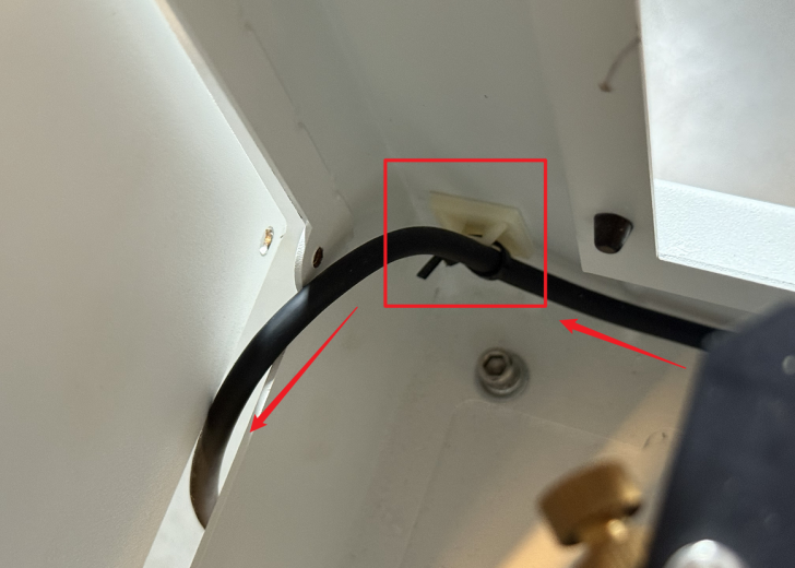
3. Open the access door/panel on the back of the device. Route the connector end of the Assembled Cable through the internal space at the back of the device. Pull it out through the cable pass-through hole in the rear cover.
IMPORTANT SAFETY WARNING:
Due to limited space in the rear cover's cable pass-through holes, improperly routed cables may intrude into the laser optical path. This poses serious risks including: laser beam reflection hazards, burned/cut wires and potential equipment damage.
REQUIRED ACTIONS:
ALL cables MUST be securely fastened using cable ties and cable tie mounts. Cable positions MUST be periodically inspected to prevent the above hazards!
4. Open the small access door/panel on the left side of the device. Pull the connector through this opening towards the Air Assist Kit. Plug the connector into the port labeled "Ctrl" to complete the circuit connection.
- Unused Wire Handling: The PUMP wire does not require connection to any terminal. Securely bundle and stow it away from moving parts or connectors.
¶ Chapter 4. Air Assist Operation Instructions
¶ 4.1 Startup & Shutdown
This air assist system features start-stop interlock control with the laser equipment:
The air assist system automatically activates / deactivates when the laser equipment is started / shut down. If the laser equipment has no active processing task, the air assist system stops air supply.
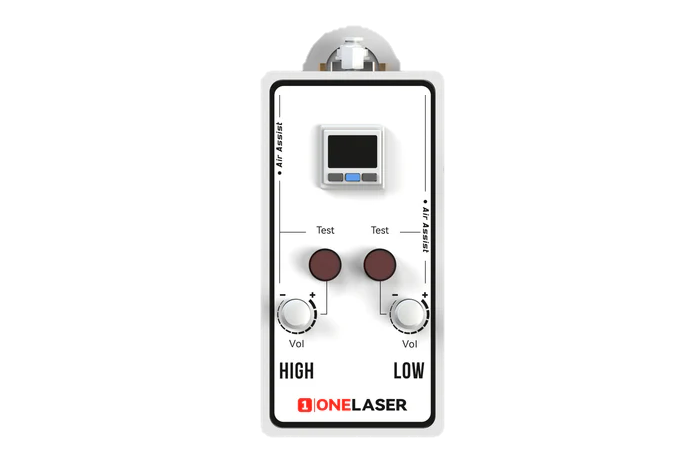
¶ 4.2 Digital Pressure Gauge
¶ 4.2.1 Panel Overview
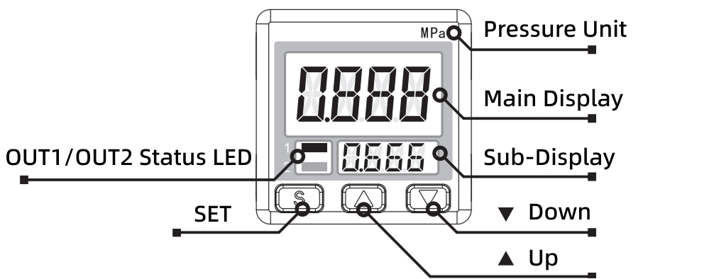
¶ 4.2.2 Function & Usage
The digital pressure gauge within this Air Assist Kit has undergone precision calibration prior to shipment. Users must not disassemble or recalibrate the gauge.
The gauge provides real-time, continuous display of the pressure value detected by the sensor. When system pressure is stable with minimal fluctuation, the gauge reading will remain clear and steady.
Important:
If you observe that the digital pressure gauge only displays up to 0.5 MPa when using a 0.6 MPa air supply, this is a normal occurrence. Pressure reduction occurs as the air enters the system, and this level of drop falls within the expected range.
¶ 4.2.3 Output Display & Error Codes
During normal operation, the gauge continuously displays the real-time air pressure value. Upon detecting a system abnormality, the screen will display one of the following error codes:
|
Error Display |
Error Description |
|
 |
Abnormal current consumption on switch output |
|
 |
Pressure applied during zero-point calibration |
|
 |
Pressure value exceeds measurement range |
|
 |
Internal Error |
|
 |
Internal Error |
If an error code appears:
DO NOT force continued operation. This may damage the laser equipment and Air Assist Kit. Please contact after-sales support personnel for resolution.
¶ 4.2.4 Safety Precautions
- Gas Compatibility: Use ONLY with non-corrosive gases. STRICTLY PROHIBITED for use with corrosive gases, flammable gases, or any liquids.
- Physical Handling: The gauge must not be subjected to dropping, impact, or severe shock. Such events may cause permanent damage to internal precision components, resulting in gauge failure.
- Input Pressure Limits: Input pressure MUST remain strictly within the specified pressure and rated voltage limits. Exceeding the upper limit will cause damage to the pressure gauge and related internal components.
- Operating Environment: DO NOT use the gauge in environments with excessive moisture, oil mist, dust, or other contaminants. Contaminant ingress can lead to internal air path blockage, corrosion of precision parts, or functional failure.
¶ 4.3 Controlling Air Assist Pressure Modes
The Air Assist Control supports controlling the auxiliary air pressure in two modes: High Pressure and Low Pressure. The air pressure settings for each mode are independent. You can control the Air Assist Control's operating mode via the following methods:
- Automatic Control via Device Processing: When the device is processing a design, it automatically controls the Air Assist Control's operating mode based on the air assist settings defined in the design layers.
- Manual Control: When the device is not in processing mode and manual control mode is inactive (both button LEDs are off), press the High-pressure air test button or the Low-pressure air test button to manually control the Air Assist Control's operating mode.
¶ 4.3.1 Setting Air Assist Control Mode in Design Software
After correct installation, the device will automatically set the Air Assist Control's pressure mode based on the air assist switch settings defined in the design layers:
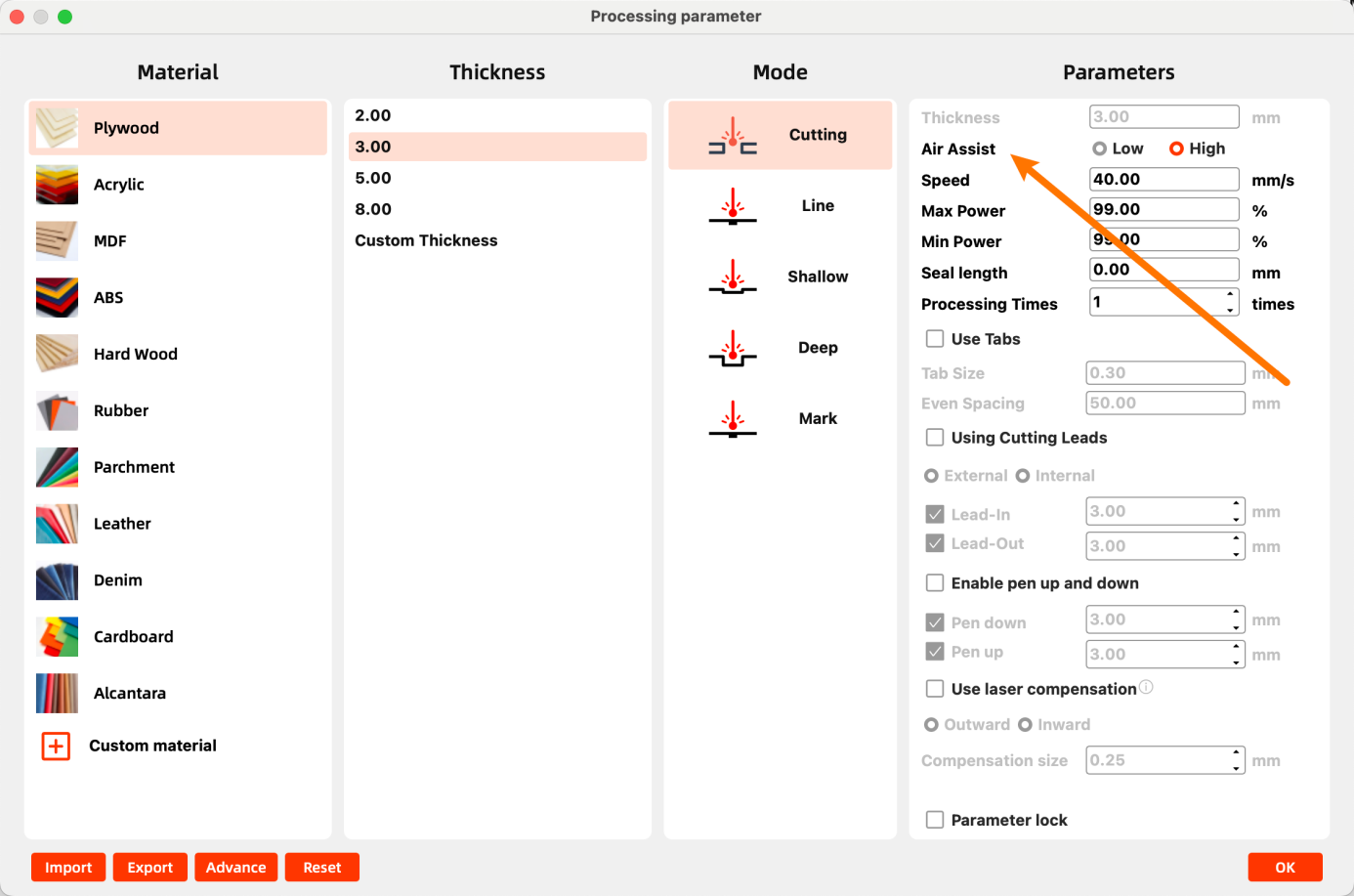
- Using MakerBoost: Double-click the design layer. In the pop-up window, set Air Assist to Low or High. Selecting High sets the layer for High-Pressure air assist. Selecting Low sets the layer for Low-Pressure air assist.
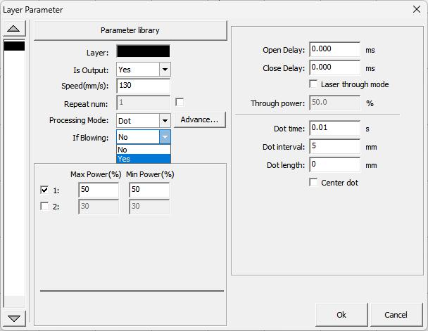
- Using RDWorks: Double-click the design layer. In the pop-up window, set If Blowing to Yes to enable High-Pressure air assist for that layer. Setting it to No enables Low-Pressure air assist.
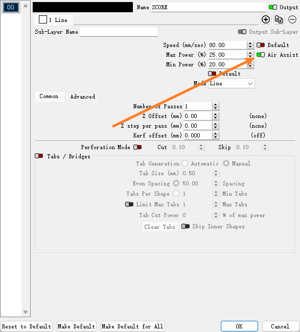
- Using LightBurn: Double-click the design layer. In the pop-up window, set Air Assist to On to enable High-Pressure air assist for that layer. Setting it to Off enables Low-Pressure air assist.
¶ 4.3.2 Adjusting High-Pressure Air Assist
- Ensure only the High-pressure air test button LED is illuminated.
- If the LED is off, press the button or ensure the device is processing with the current layer set to Air Assist ON (High).
- Pull up the High-pressure air adjustment knob to disengage its lock.
- Rotate clockwise to increase High-Pressure air assist. Rotate counterclockwise to decrease High-Pressure air assist.
- Observe the value on the digital display until the desired pressure is reached.
- Push down the knob to re-engage its lock.
¶ 4.3.3 Adjusting Low-Pressure Air Assist
- Ensure only the Low-pressure air test button LED is illuminated.
- If the LED is off, press the button or ensure the device is processing with the current layer set to Air Assist ON (Low).
- Pull up the Low-pressure air adjustment knob to disengage its lock.
- Rotate clockwise to increase Low-Pressure air assist. Rotate counterclockwise to decrease Low-Pressure air assist.
- Observe the value on the digital display until the desired pressure is reached.
- Push down the knob to re-engage its lock.
¶ 4.3.4 Low-Pressure Operation Protection
Typically, higher air pressure is used for cutting operations, while lower pressure yields better results for engraving operations. You can adjust the air pressure to meet specific requirements via manual knob adjustment or by changing the air assist mode in your design.
Critical Protection Mechanism:
- When air assist pressure is too low (supply pressure < 0.3 psi / ~2.07 kPa) or air supply is interrupted, the airflow from the laser nozzle may be insufficient to protect the lens and nozzle from smoke and debris contamination.
- Under these conditions, the Air Assist Control will automatically halt operation and may display a warning message on the screen.
- Re-adjust the corresponding pressure adjustment knob until the pressure display returns to a green (normal) indication, then resume processing.
¶ 4.4 Troubleshooting
If the following issues occur during use, contact After-Sales Service:
|
Symptom |
Possible Cause |
|
Pressure reads 0 / No airflow |
Main gas supply valve closed / Air hose kinked or detached / Filter blocked |
|
Abnormal pressure fluctuation |
Insufficient source pressure / Air filter regulator malfunction |
|
Abnormal noise |
Accumulated dust in cooling fan / Overload from continuous operation |
|
Digital gauge black screen |
Power disconnected / Loose display ribbon cable |