¶ ONELASER VertiGO - Machine Installation and User Guide
This manual has been designated as the ONELASER VertiGO machine installation and user guide.
The manual is divided into five chapters, including general information instructions, safety instructions, the key components of every laser cutting systems and the installation steps, operation instructions and maintenance instructions from ONELASER Kraft Engineering Crop.
Important Notice:
For safe operation and optimal performance of your VertiGO machine, you MUST strictly follow all specifications and ONELASER's installation requirements.
Failure to do so may result in:
- Reduced performance and poor results
- Shortened machine lifespan
- Higher maintenance costs
- Serious machine damage
- Potential safety hazards
This manual provides the essential installation specifications. We strongly advise that all users read and fully understand every instruction and warning in this guide before installing or operating the machine.
Need Help?
If you encounter any issues during installation, contact our technical support team immediately.
¶ Contents
- Chapter 1. General
- Chapter 2. Safety
- Chapter 3. Process of Installing
- Chapter 4. Operation
- Chapter 5. Maintenance
¶ Chapter 1. General
¶ 1.1 Safety Information
Carefully read this entire document before installing and operating the machine.
WARNING:
Failure to read, thoroughly understand, and strictly adhere to the instructions in this operation manual may result in serious personal injury, death, property damage, fire, electric shock, machine malfunction, degraded performance, reduced machine lifespan, or severe damage to the machine!
The following symbols and notes are used to alert users to potential hazards and critical operational information. Pay close attention:

High Voltage:
There is a risk of electric shock. This device can only be maintained by professionals.
Laser Radiation:
This device has laser radiation function. Please pay attention to the danger of laser beam. Please avoid direct exposure of eyes or skin to laser during operation. Be sure to follow the safe operating procedures to prevent personal injury or machine damage.
CAUTION:
1. Use Only Approved Parts: When replacing machine components, only use the components or spare parts provided or listed in the associated parts list. The use of third-party components may lead to abnormal machine performance, increased safety risks, and may void the product warranty.
2. Follow Auxiliary machine Instructions: Auxiliary machine supplied with this device is accompanied by its own dedicated instruction manual. Installation or operation of any auxiliary machine must strictly comply with the requirements specified in its respective manual. (Contact us if you require related information).
¶ 1.2 Compatible Materials
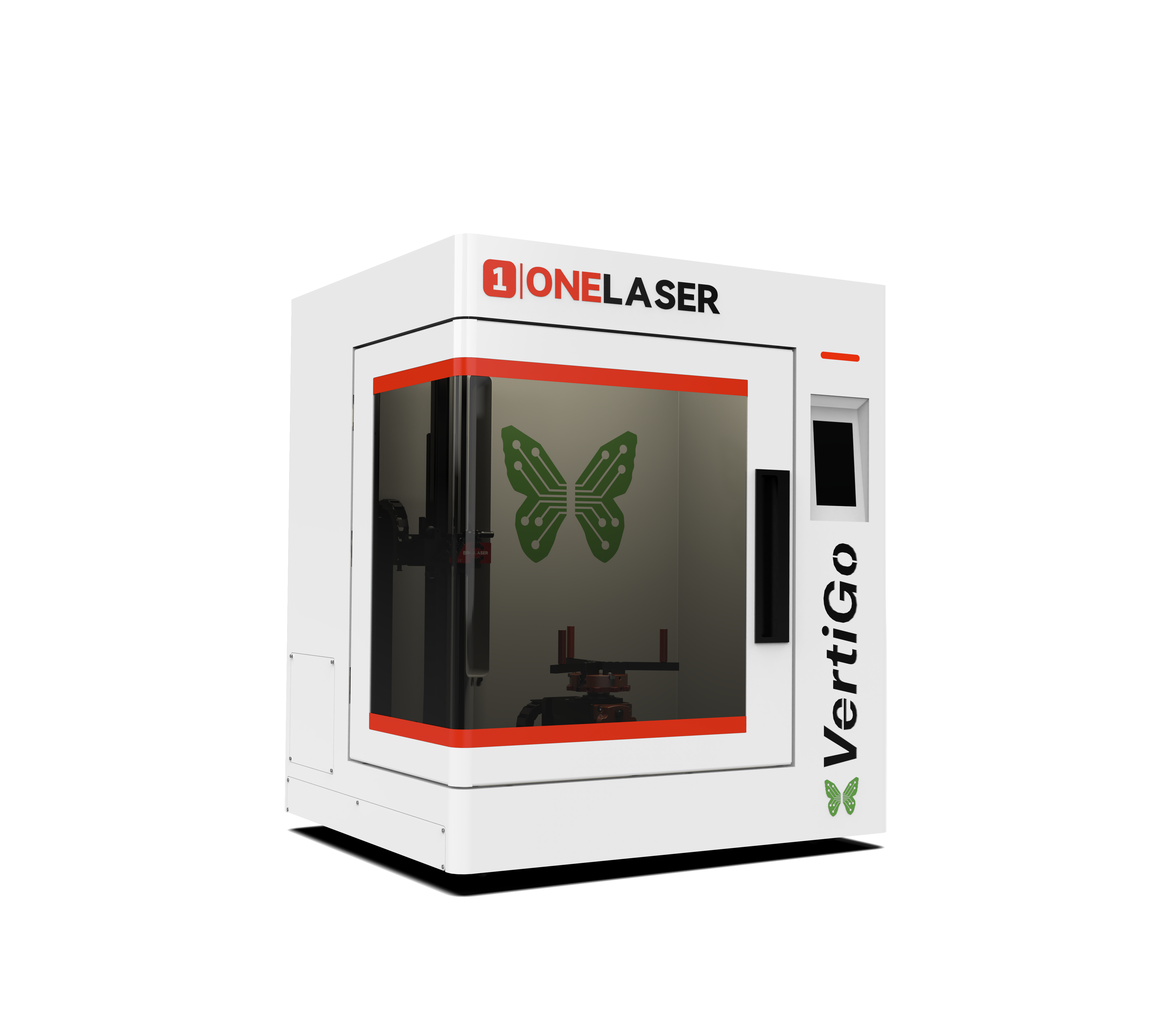
VertiGO is used for engraving of thermos cup.
A wide variety of materials such as rubber, acrylic, coated metal, tin, special steel, anodized aluminum, cork, cardboard, glass, several plastics and wood can be processed on the laser.

Notice:
1.The engraving process must only be performed with a perfectly adjusted machine.
2.Use of the system in other areas is against the designated use. The manufacturer does not admit liability for damage to personal and/or machine resulting from such use.
3.The system must only be operated, maintained and repaired, by personnel that are familiar with the designated field of use and the dangers of the machine!
4.Non-observance of the instructions for operation, maintenance and repair described in this Operation Manual excludes any liability of the manufacturer if a defect occurs.
5.Caution when processing conductive materials (carbon fibers). Conductive dust or particles in the ambient air might damage electrical components and lead to short circuits. Bear in mind that those defects are not warranted.
¶ 1.3 Specifications
Mechanics
|
|
VertiGO |
|
Max. Speed |
800mm/s |
|
Max. Acceleration |
3G |
|
DPI |
1000 |
|
Laser Type |
38W Sealed Radio Frequency Laser Tube |
|
Z Axis Distance |
165mm / 6.50” |
|
Maximum Lifting Height |
300mm / 11.81” |
|
Maximum Machining Size |
Diameter 89~293mm / 3.5”~11.54” |
|
Net Weight |
64kg |
|
Standard Head |
2.5’’ |
|
Lens Diameter |
20mm / 0.79” |
|
Mirror Diameter |
25mm / 0.98” |
Outer Dimensions
|
|
VertiGO |
|
W x D x H |
630*550*710mm 24.8”x 21.65”x 27.95” |
Control System
|
|
VertiGO |
|
Interface Hardware |
USB: connect to PC Ethernet: connect to PC WI-FI:connect to PC |
|
Interface Software |
MakerBoost, RDWorks, LightBurn |
Electricity, Power, Breaker
|
|
VertiGO |
|
Electricity Requirement |
100-240V AC, 50 or 60Hz, Single phase Machine requires either 115v or 220V voltage(customized from factory); Support both 50Hz and 60Hz, single phase |
|
Power Consumption |
706.2W, 115V 660.5W, 220V |
Ambient Conditions
|
|
VertiGO |
|
Ambient Temperature |
+15°C to +35°C / 59°F to 95°F |
Laser Safety
|
|
VertiGO |
|
Laser Class |
Laser Class II |
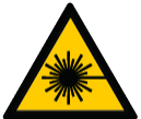
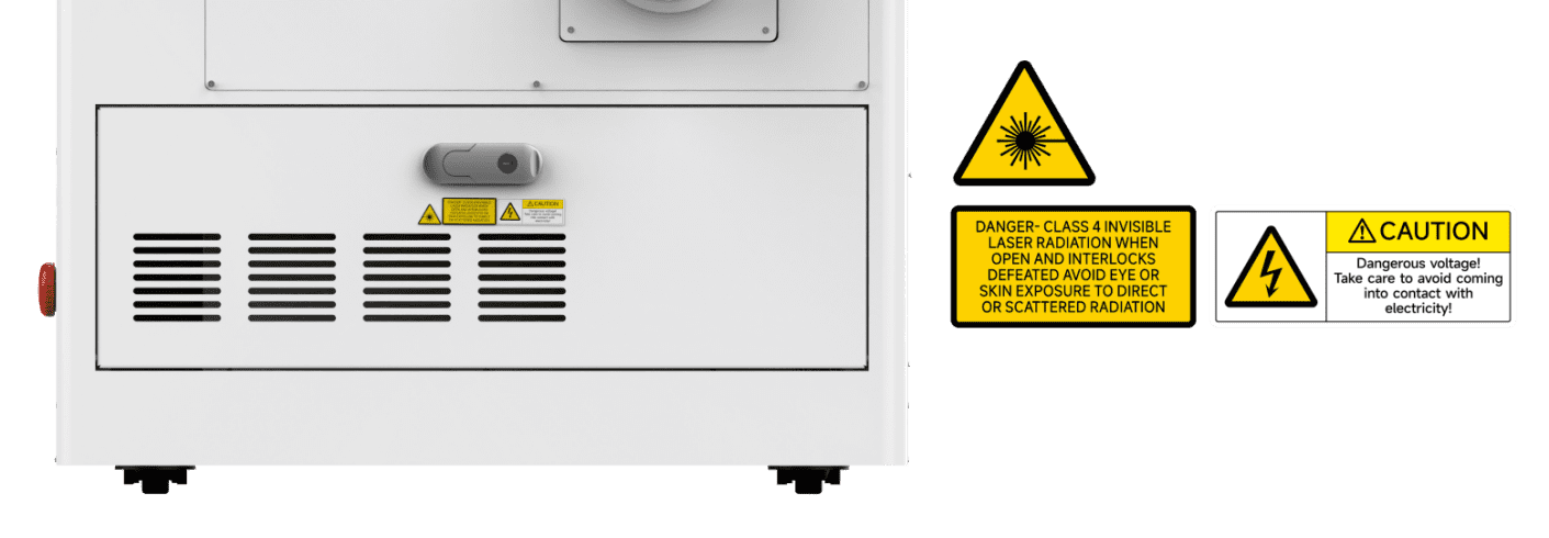
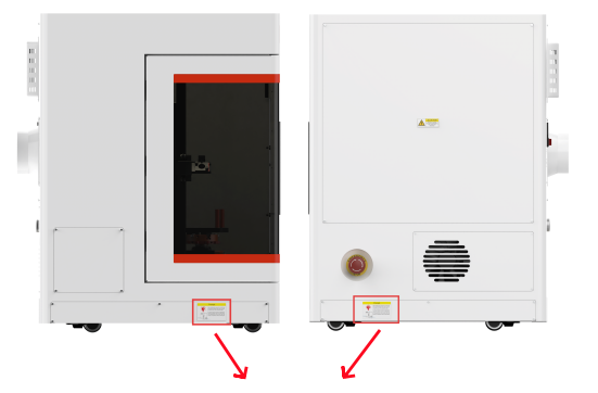
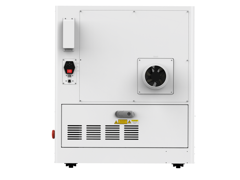
¶ 1.4 Machine Nameplate
The manufacturer's information is located on the rear of the unit (see diagram below). Retain all data plate information for future reference. You may be required to provide the serial number when contacting our support team.
¶ Chapter 2. Safety
¶ 2.1 General Safety Regulations
All personnel involved in machine installation, commissioning, operation, maintenance, or repair must thoroughly read and understand the operation manual (with emphasis on the "Safety Regulations" section). Enterprise users are reminded that internal safety procedures must be established based on personnel qualifications, and written confirmation must be obtained verifying that relevant personnel have completed manual training certification.
Safety Operation Responsibilities
Only trained personnel are permitted to operate the machine. During installation, commissioning, startup/shutdown, operation, parameter modification, maintenance, or inspection, safety shutdown procedures specified in the operation manual must be strictly followed.
User/Operator Safety Rules:
1. Any operation endangering machine safety is strictly prohibited.
2. Operators must ensure the machine is not operated by unauthorized personnel.
3. Operators bear responsibility for pre-operation checks: Confirm no visible damage or defects; immediately report any safety hazards (including operational abnormalities).
4. Users must ensure the machine continuously operates in a safe state.
5. Users must maintain cleanliness (internal/external) and clear operational pathways through standardized procedures.
6. Safety devices must never be removed or disabled (risk of irreversible injury: severe burns, blindness, etc.). If disassembly is necessary for maintenance, immediate restoration post-work is mandatory.
7. Activities like commissioning, modification, reconfiguration, or maintenance must be performed by certified personnel with power disconnected.
8. Any unauthorized modification may void the warranty (excluding preventive maintenance, calibration, and adjustments performed per ONELASER specifications).
¶ 2.2 Laser Safety Information
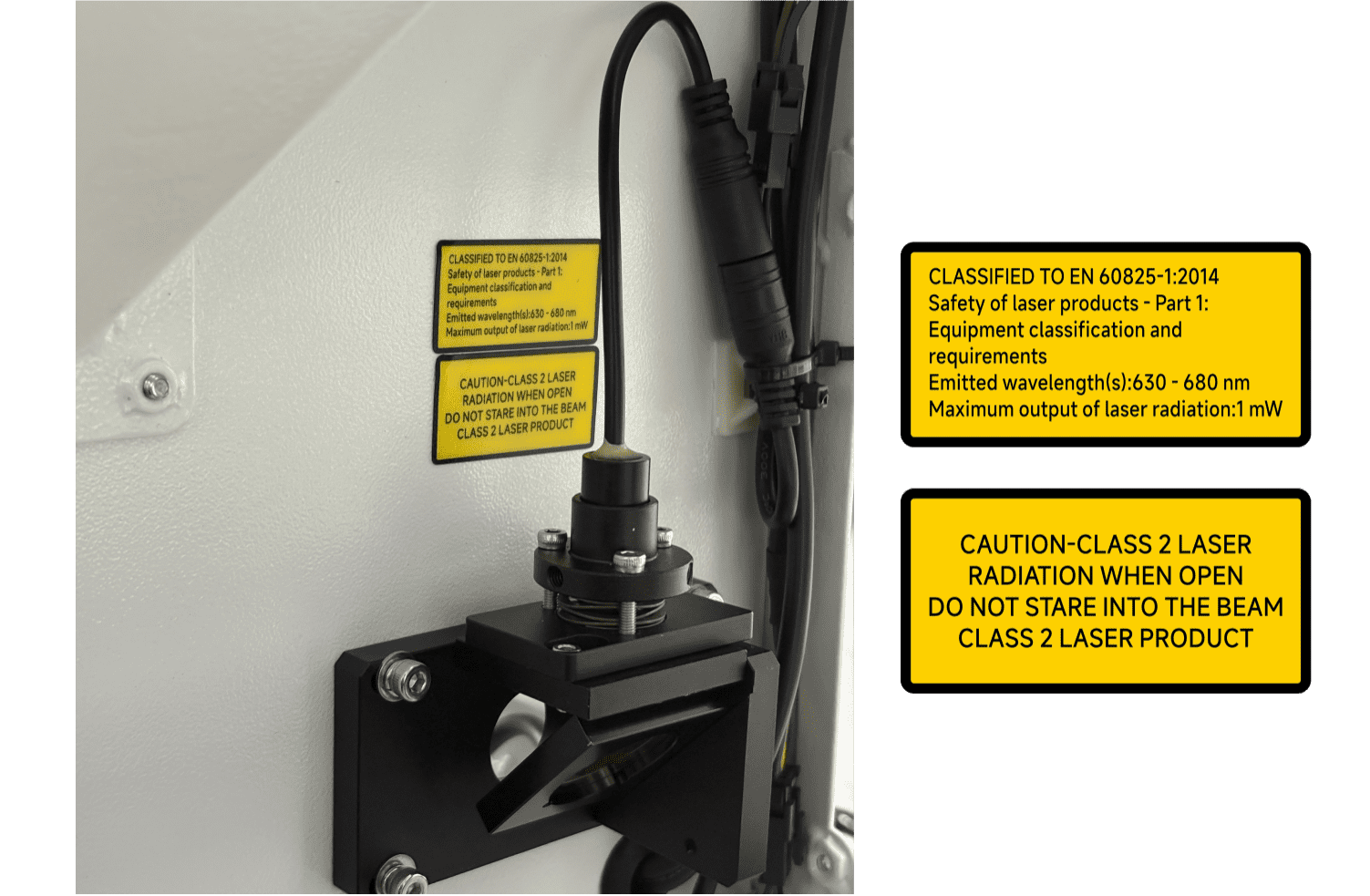
1.VertiGO is classified as a Class II laser product according to international safety standards. This classification indicates the laser system is safe during normal operation due to its protective housing and integrated safety features.
Critical Warning:
Tampering with safety features, performing unauthorized modifications, or operating the device improperly can override the Class II safety design. This may result in the emission of harmful, hazardous laser radiation, posing a serious risk of eye and skin injury.
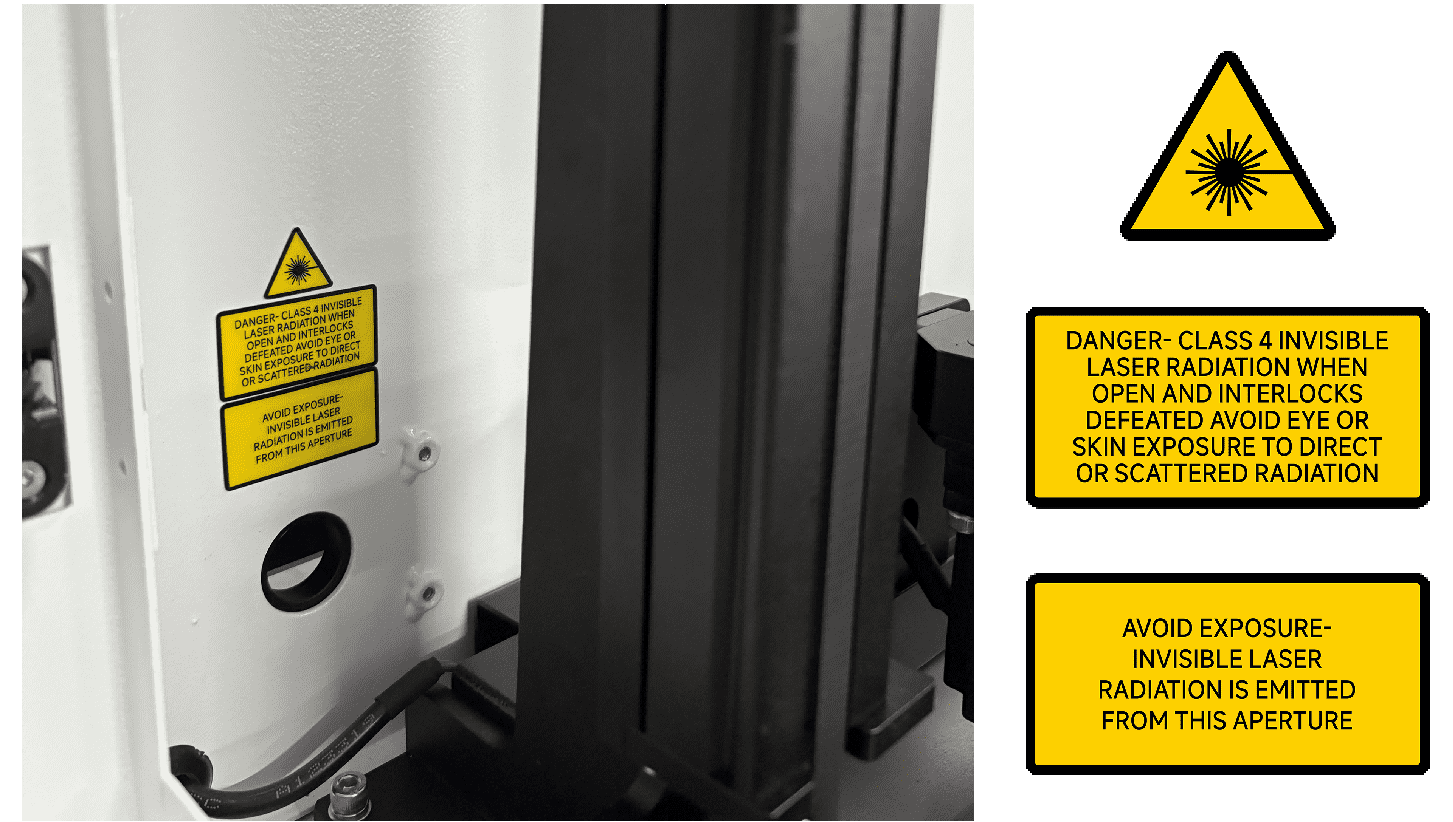
2.This laser engraving system contains a carbon dioxide (CO2) laser of Class IV that emits intensive and invisible laser radiation. Without safety precautions the direct radiation or even diffuse reflected radiation is dangerous!
3.Without safety precautions, the following risks exist with exposure to laser radiation:
Eyes: Burns to the cornea / Skin: Burns / Clothing: Danger of fire
4.Never try to modify or disassemble the laser and do not try to start up a system that had been modified or disassembled!
5.Dangerous radiation exposure can result from the use of operation or adjustment machine other than that described here, and if different operational methods are performed.
¶ 2.3 Safety Precautions when Operating the Device
VertiGO has an integrated safety system which immediately stops the job when the protection cover (Lid) is opened. An incomplete job will occur if the cover is opened during operation. Press the "PAUSE" button first if you want to interrupt an engraving process.
Please remember the following safety precautions when working with this device:

1.CO2 Fire extinguishers should be placed near laser. Always keep a properly maintained and inspected fire extinguisher on hand.
2.Do not store any flammable materials in the inside of the device. Particularly leftovers of produced materials have to be removed to prevent fire hazard.
3.Please maintain free airflow around this system at all times. Do not cover the machine while in operation.
4.Stay with the laser. Do not leave the laser unattended when it is working, small scraps can ignite and without supervision can destroy the machine if not checked.
5.Use Air Assist. Always use the system’ s Air Assist feature when vector cutting.
1.These lasers emit invisible radiation; safety glasses should be worn when maintaining these machines for your protection.
2.Adjustment of the beam path must be performed only by specially trained personnel. An improper setting can lead to uncontrolled emission of the laser radiation.
1.Do not disable limit switches or safety features as this can invalidate warranties and cause damage to you and the machine.
2.Before processing materials, the user must: Verify if harmful materials will be generated and if the exhaust system's filters are suitable for them. Select filters and the exhaust system based on national/regional threshold limits for dust, mist, and gases (ensuring maximum workplace concentration values are not exceeded).
3.PVC (polyvinyl chloride) must under no circumstances be processed with the laser.
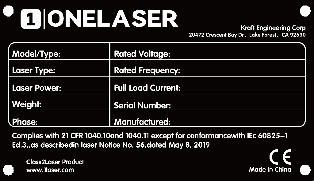
¶ 2.4 Warning and Information Labels
The warning and information labels in various locations if the machine should always be read carefully and understood. If labels are lost or damaged, they must be replaced immediately.

¶ Chapter 3. Process of Installing
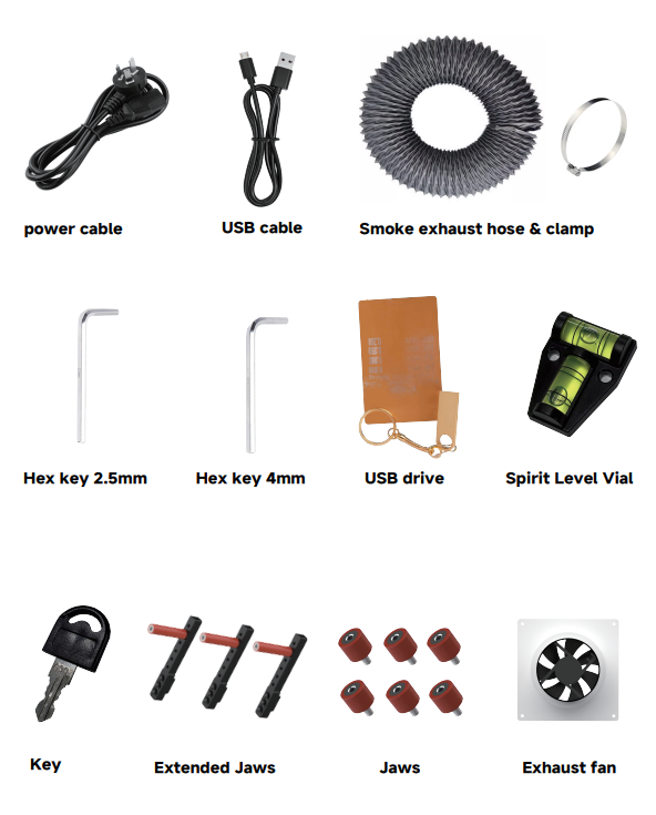
¶ 3.1 List of Items
Check if the accessories include the following items:
¶ 3.2 Side Baffles Installation Requirements
The side baffles on both sides of the equipment will be packed separately when shipped.
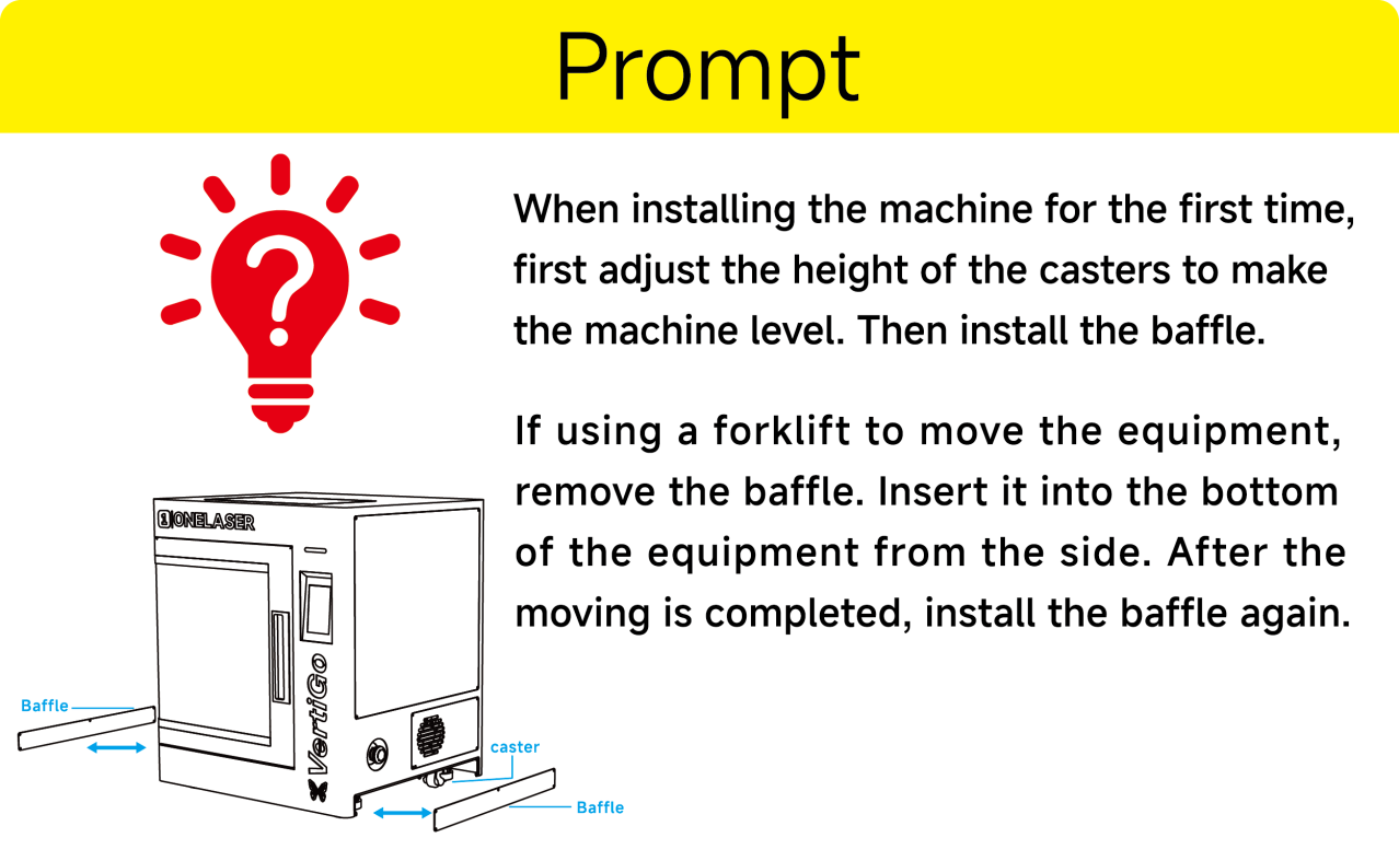
- When installing the machine for the first time, first adjust the height of the casters to make the machine level.
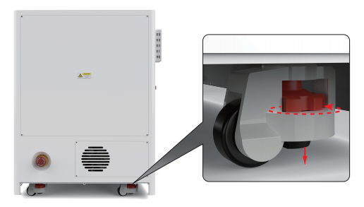
- Then install the baffle.
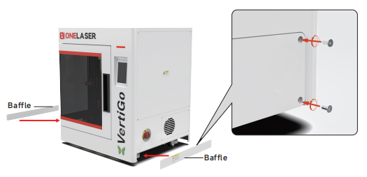
- If using a forklift to move the equipment, remove the baffle. Insert it into the bottom of the equipment from the side. After the moving is completed, install the baffle again.
¶ 3.3 Exhaust System Requirements
Effective smoke extraction is essential for removing hazardous combustible fumes generated during laser processing. This machine must be equipped with a safety-compliant exhaust system including:
- A blower meeting rated flow capacity, duty cycle, and airflow requirements
- Correctly installed ducting and accessories
- (Recommended) An inline filtration system for efficient removal of fine particulates and odors.
Do not start the machine without an adequate exhaust system.
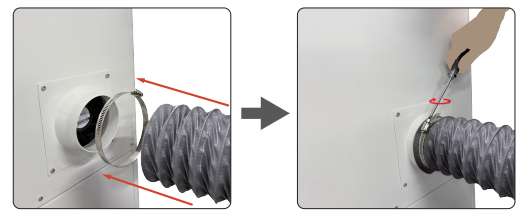
The installation steps for the standard exhaust fan and exhaust pipe are shown in the following diagram:
- After the wires are connected, install the exhaust fan and tighten the fixing screws.
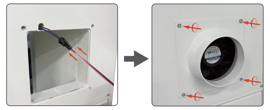
- Install exhaust pipe.
¶ 3.4 Computer Requirements
The following recommendation represents the minimum requirements. When using a more powerful computer the graphics are generated and displayed faster and the computing times and the data transfer to the laser are reduced. To use the newest software version, you might have to abide other requirements.
Minimum system requirements (based on Qt 6.8.3 program):
|
|
MacOS |
Windows |
|
Operating System |
macOS 12 or later |
Windows 10 ( 64 bit ) or later
|
|
RAM |
4GB or higher |
4GB or higher |
|
Processor |
Apple M series |
x86 64 architecture,Intel Core 2 Duo / AMD 64-bit processor or higher |
|
Display |
1400 x 1050 or higher monitor resolution |
1400 x 1050 or higher monitor resolution |
|
Storage |
At least 1 GB of available space |
At least 1 GB of available space |
|
Connectivity Interfaces |
1 free USB interface (for supporting external devices) |
1 free USB interface (for supporting external devices) |
Recommended configuration (for a smoother experience):
|
|
MacOS |
Windows |
|
Operating System |
macOS 13 or later |
Windows 11 ( 64 bit )
|
|
RAM |
8GB or higher |
8GB or higher |
|
Processor |
Apple Ml / M2 series or higher |
Intel i5 8th Generation / AMD Ryzen 5 or higher |
|
Display |
1920 x 1080 or higher monitor resolution |
1920 x 1080 or higher monitor resolution |
|
Storage |
SSD, with at least 2GB of available space |
SSD, with at least 2GB of available space |
|
Connectivity Interfaces |
1 free USB interface (for supporting external devices) |
1 free USB interface (for supporting external devices) |
¶ 3.5 Connecting the Mains
Perform the connections exactly in the order described; otherwise electrostatic charging can damage your computer and/or the electronics of the laser system.
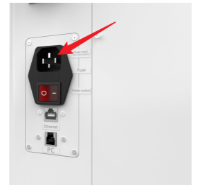
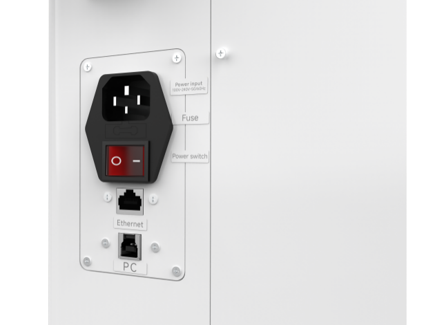
Connect one end of the mains cable with the connection socket named “Power Input” at the rear side of the laser device (see the right figure) and the other end with a protected power outlet.
Mains voltage and operating voltage must correspond (AC 100V-240V 50-60Hz). Under no circumstances should you switch on the device if the voltages do not correspond.
¶ Chapter 4. Operation
¶ 4.1 Machine View
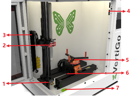
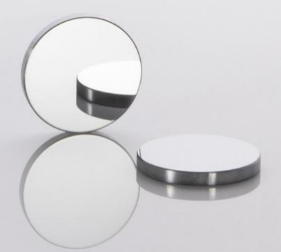
1.Mirror
The laser beam is reflected by the mirror to the laser head.
2.Laser Head
Laser beam and red dot pointer are all come
out from the laser head.
3.Drag Chain
Protects and guides cables in moving machinery.
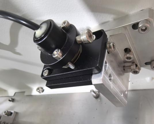
4.Door Protection Sensor
Laser will stop working once the cover is opened during working. The sensor is also installed in the same place on the left side.
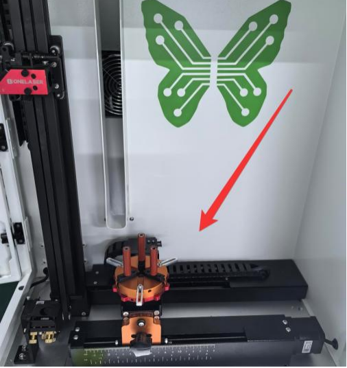
5.Rotary Fixture
This is used to clamp the workpiece and utilize the rotating function to complete engraving.
6.Z Axis (left and right movement)
The motion system is that performs the
mechanical movements in Z direction.
7.Spirit Level
The spirit level is used to indicate whether the device is balanced and can be used when using a caster to adjust the level.
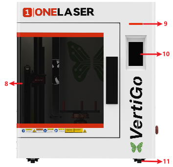
8.Flap
If the flap is opened, no data is processed. When the protection cover is opened during working, the motion system is stopped and the laser source is turned off. During processing of commands the protection cover must only be opened after pressing the “Pause” button.
9.Indicator Light
A green light illuminates when the machine is operating.
10.Control Panel
You can control the H-axis, F-axis and R-axis manually by the display panel, it also shows the working time, machine status, location and affords many function options.
11.Caster
The casters facilitate the movement of the device and are used to adjust the balance of the device.
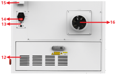
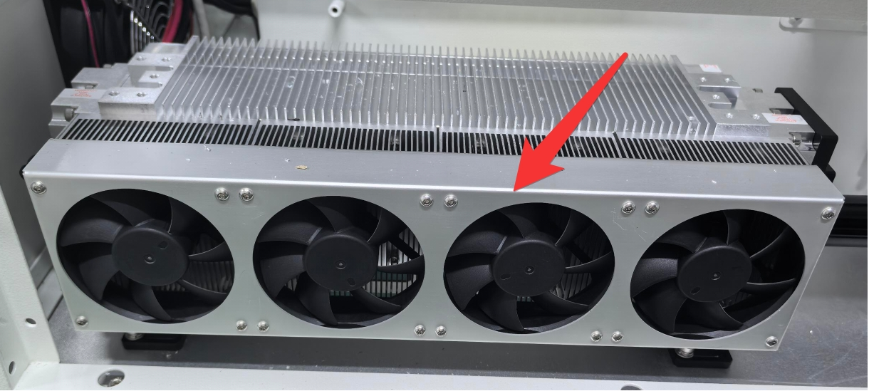
12. Cooling Fan
Cooling the Internal components.
13.PC and Ethernet Connection Port
Connect machine with PC cable and Ethernet cable.
14.Main Switch
Power on or off the machine.
15.WiFi Router
Used to receive WiFi signals.
16.Exhaust Fan
Connect the exhaust pipe.
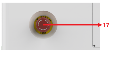
17.Emergency-stop
Once there’s an accident happen (laser catch fire, laser out leakage) during working, please turn off this switch immediately. It will be cut off the laser power and motion power immediately.
¶ 4.2 ON/OFF Switch
MUST confirm these conditions BEFORE powering on the equipment:
1. Clear the work area: Remove all materials and foreign objects from the worktable and laser head travel paths to prevent collision damage during homing.
2. Secure enclosures: Ensure all doors and access panels are closed and secured.
3. Verify auxiliary systems: Confirm exhaust/cooling systems are operating normally.
Startup Sequence:
4. Press the Power Switch to ON position.
5. The control panel will initialize while the laser head performs homing.
6. When the home screen appears, the system is ready for operation.
¶ 4.3 Make Connection between PC and Machine
¶ 4.3.1 Software Installation
MakerBoost
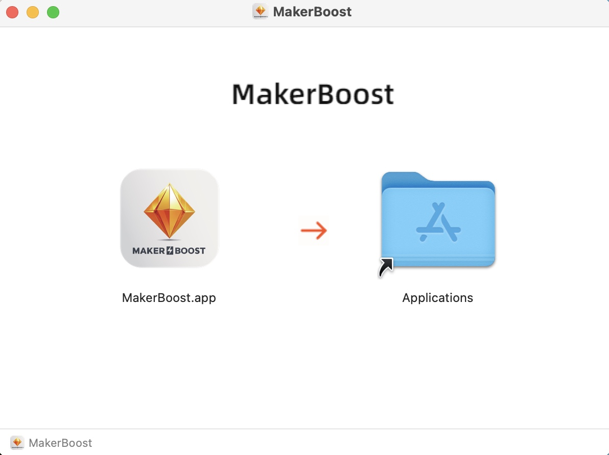
Mac:
Click to download the file. Drag the software on the left into the folder on the right. The software has been downloaded successfully. You can find it in the Launchpad and use it.
Win:
During installation, check the box for "Install device USB driver". Wait for the driver to download automatically. Finally, click "Finish" to complete the installation.
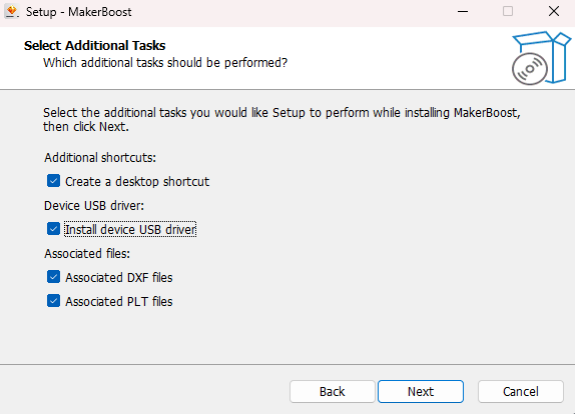
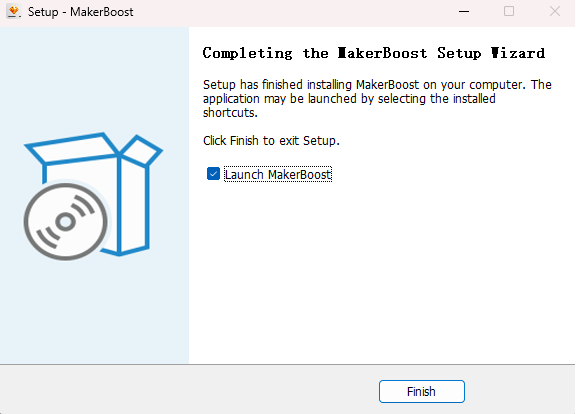
The "MakerBoost" desktop icon will be created automatically. The software is now ready for use.
Lightburn
Please download the corresponding Lightburn at the link below:
https://lightburnsoftware.com/pages/download-trial
If you use USB cable connection, please install the USB driver.
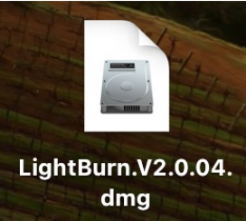
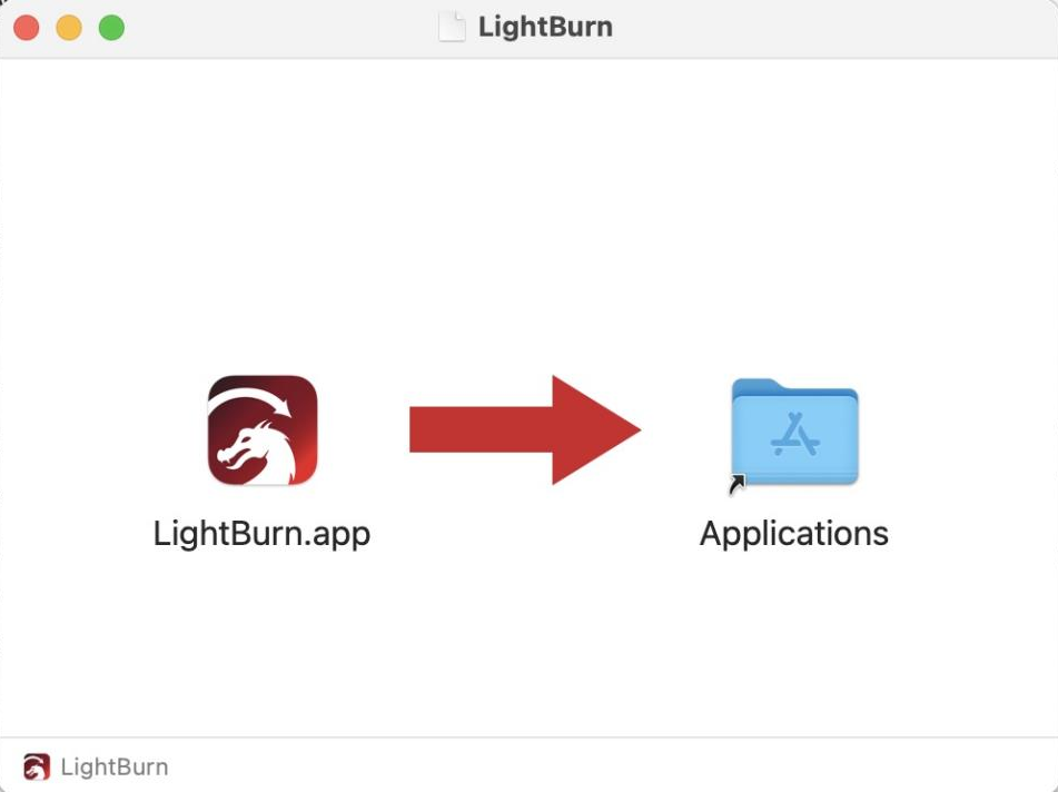
Mac:
Click to download the file. Drag the software on the left into the folder on the right. The software has been downloaded successfully. You can find it in the Launchpad and use it.
Win:
After selecting your options, click "Finish" and then wait for the driver download to complete. You can confirm this and then end the installation process.
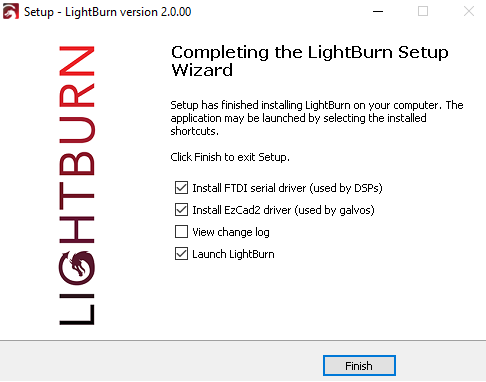
A "Lightburn" icon will be automatically added to your Desktop, you are now ready to use the Lightburn.
¶ 4.3.2 Wired Connection
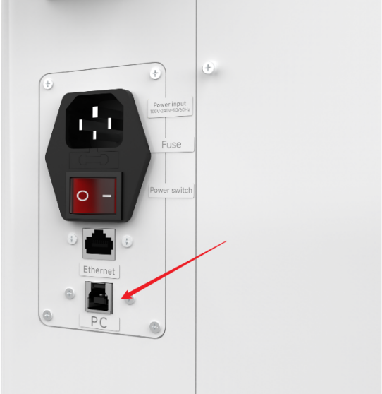
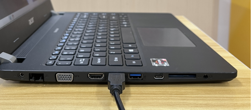
USB Cable Connection
Connecting the Computer and the machine by using the USB cable. Like below (Please use a docking station or adapter to connect for MacOS):
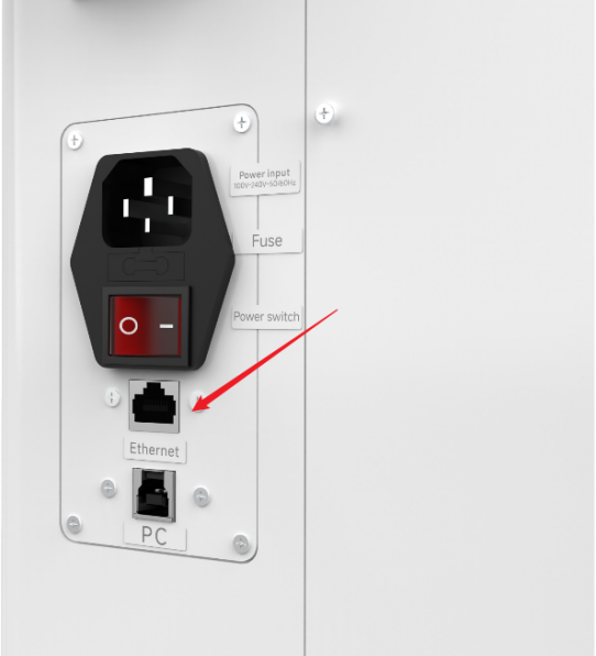
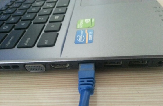
Ethernet Cable Connection
Connecting the Computer and the machine by using the Ethernet cable. Like below (Please use a docking station or adapter to connect for MacOS):
To establish communication between the PC and machine via the above methods, follow these steps:
MakerBoost
Make sure that you have your PC connected to the machine via USB cable or Ethernet cable.
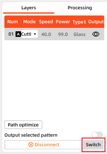
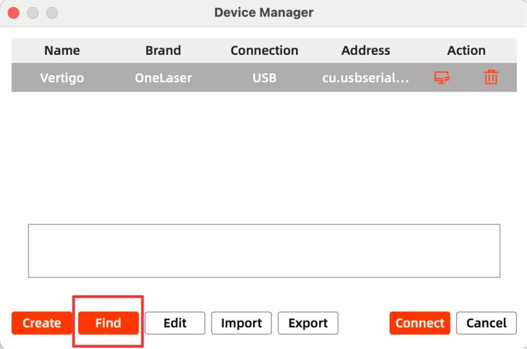
Click "Switch" from right bottom corner of the software, then click "Find" to set up by the Devices setting.
Mac:
Win:

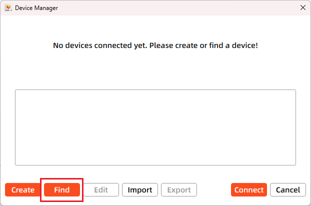
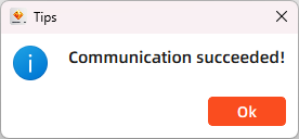
Then follow instructions to complete the connection steps step by step. Select the connection you just created and the display shows "Communication Succeeded" to indicate a successful connection. Now MakerBoost communicates with your laser machine via USB cable or Ethernet cable.
Lightburn
Make sure that you have your PC connected to the machine via USB cable or Ethernet cable.
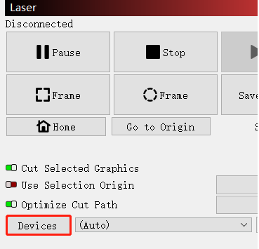
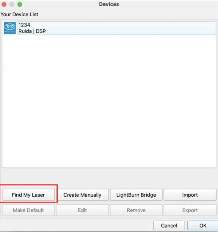
Click "Devices" from right bottom corner of the software. Click "Find My Laser" to set up by the Devices setting.
Mac:
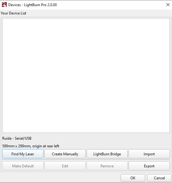
Win:

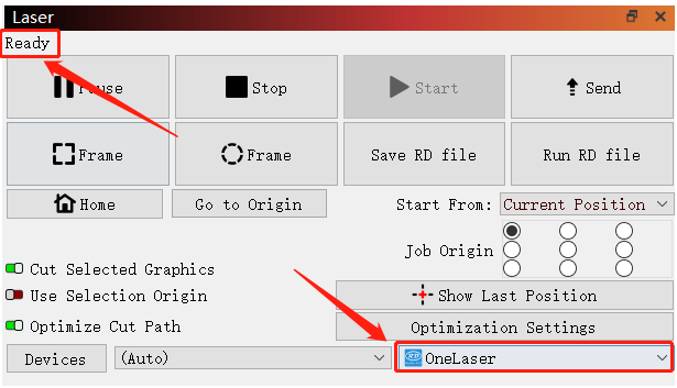
Then follow instructions to complete the connection steps step by step. Select the connection you just created and the display shows "Ready" to indicate a successful connection. Now Lightburn communicates with your laser machine via USB cable or Ethernet cable.

When connecting the machine and the PC for the first time, it may take a few minutes for the operating system to recognize the machine and install the driver.
¶ 4.3.3 Remote Connection
Network Cable Connection
Connect both the VertiGO and computer to the network using Ethernet cables.
Critical: Ensure they reside on the same subnet (e.g., 192.168.1. XXX).
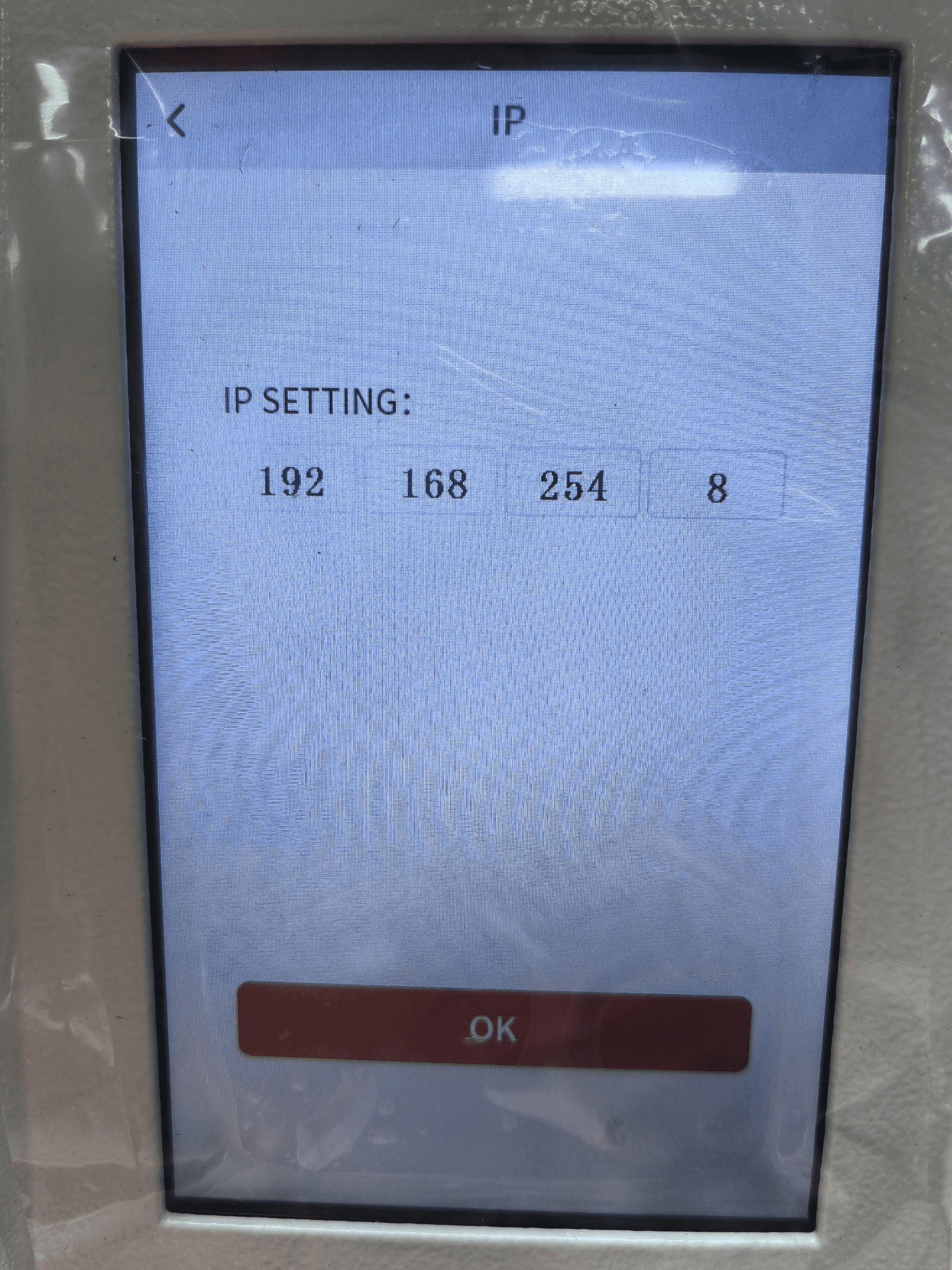
How to Viewing/Modifying VertiGO IP Address?
To establish communication between the PC and machine via the above methods, follow these steps:
MakerBoost
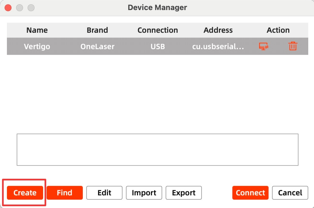
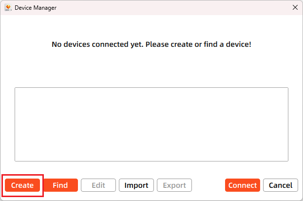
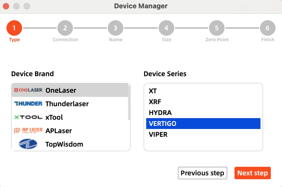
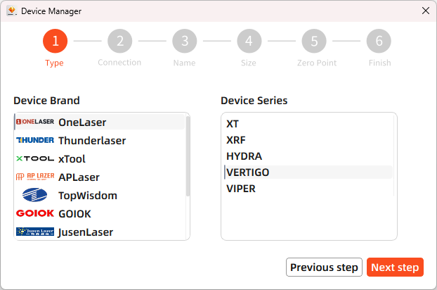
Click "Switch" from right bottom corner of the software, then click "Create" to set up by the Devices setting.
Mac:
Win:
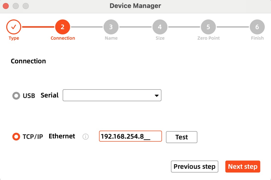
Then follow instructions to complete the connection steps step by step.
Critical: The entered IP MUST exactly match the VertiGo's configured address.
Mac:
Win:
After successful device creation, select the newly created "VertiGO" entry in the machine list. Then click the "Connect" button. The software will instantly activate the connection.
Lightburn
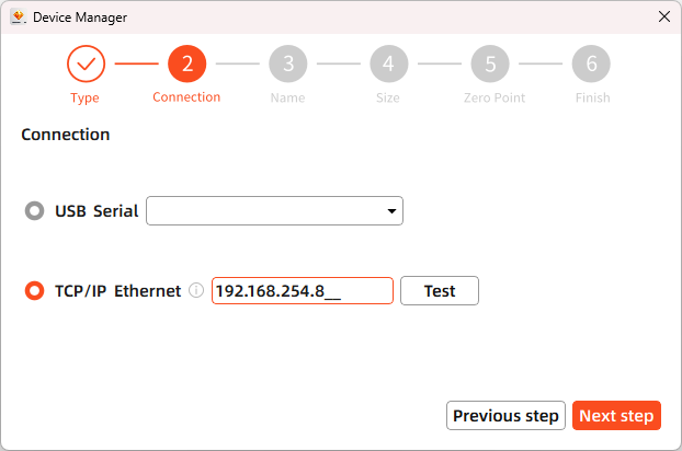
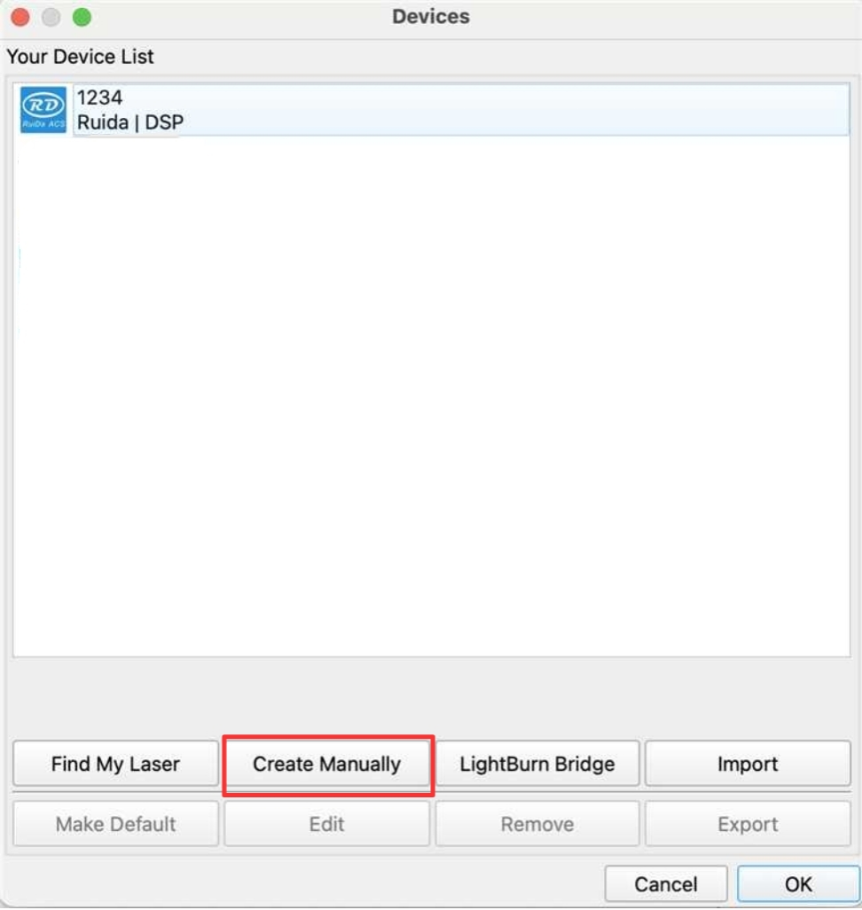
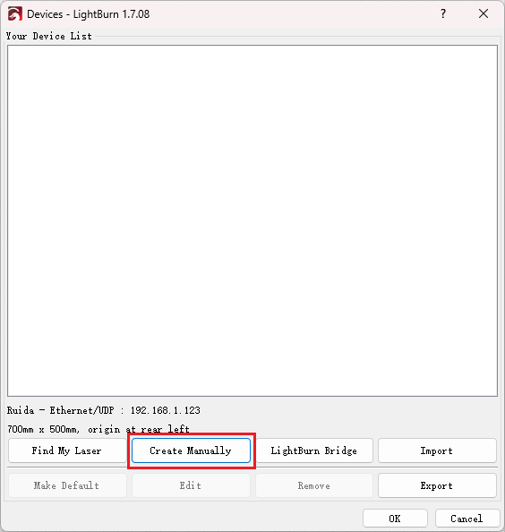
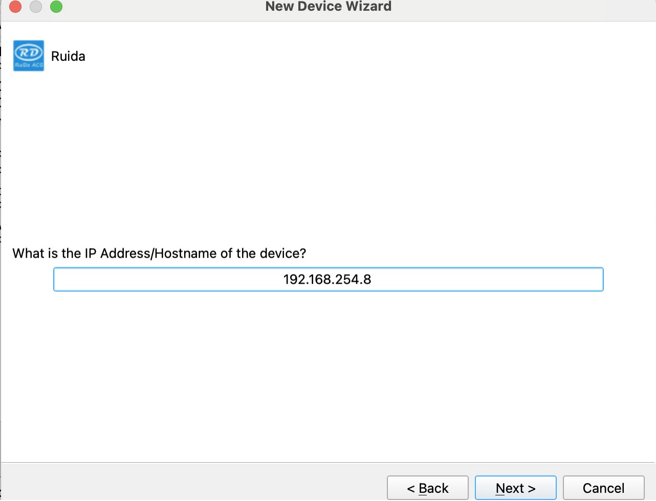
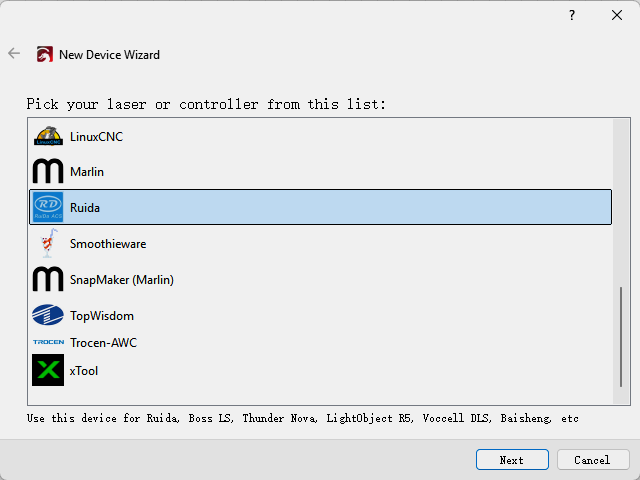
Click "Devices" from right bottom corner of the software. Click "Create Manually" to set up by the Devices setting.
Mac:
Win:
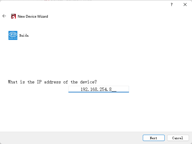
Then follow instructions to complete the connection steps step by step.
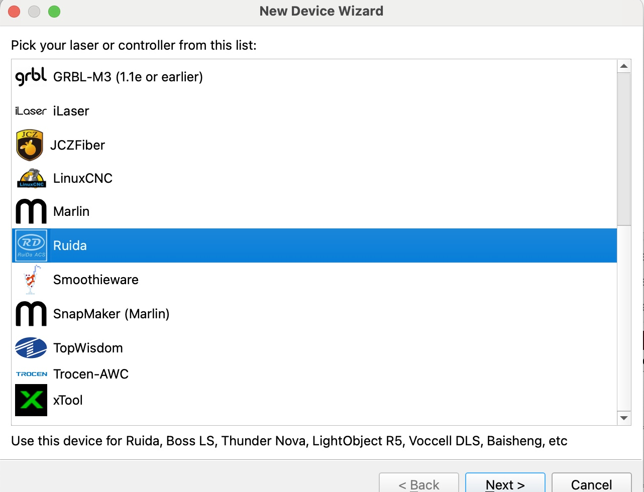
Critical: Under Controller Type dropdown, MUST select "Ruida". The entered IP MUST exactly match the VertiGo's configured address.
Mac:
Win:
After successful device creation, locate and select the newly created "VertiGO" entry in the bottom-right panel (Device List section).

WIFI Connection
The system supports two WiFi modes: Hotspot Mode and Repeater Mode.
1. Hotspot Mode
Connect your computer directly to the VertiGo's built-in router:
- SSID Format: [Machine Model]_Hotspot_[Last 5 digits of S/N]
(Example: HYDRA70_Hotspot_8A2B4)
- Default Password: 12345678
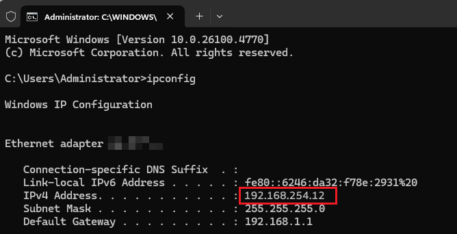
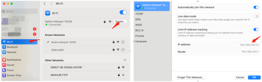
The hotspot's default IP subnet is 192.168.254.xxx. Set VertiGo's IP address within 192.168.254.xxx. Important: The last octet of the hotspot's IP must differ from VertiGo's IP address.
To verify the hotspot subnet on your computer:
①Windows: Open Command Prompt, type "ipconfig", and check the IPv4 address.
②Open WiFi settings, view network details, and locate "IP address".
How to Viewing/Modifying VertiGO IP Address?
2. Repeater Mode
Users can bridge the VertiGo's WiFi module to their primary router network. This allows both the VertiGo and computer to connect remotely via the user's regular WiFi.
Setup Procedure:
1.Connect your computer to the VertiGo's hotspot:
- SSID: [Machine Model]_Hotspot_[Last 5 S/N digits]
- Password: 12345678
2.Open a web browser and enter: 192.168.254.254 or http://vonets.cfg


3.Log in to the bridge device console:
- Username: admin
- Password: admin
- Click "Login"
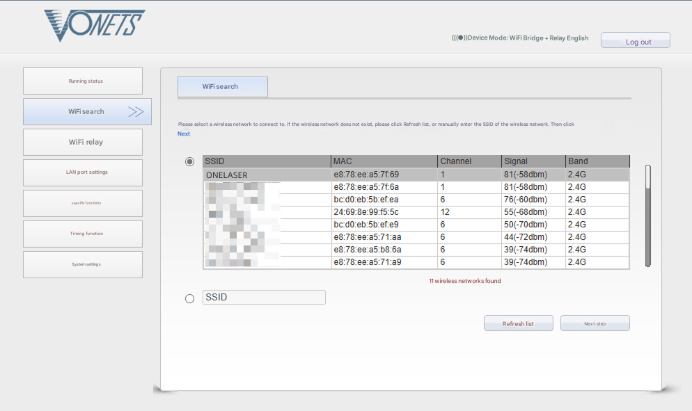
4.Configure bridging:
- Click "WIFI Search"
- Select your target WiFi network
- Click "Next"
5.Enter the target WiFi's password. Check and disable hotspot. Do not modify advanced/other settings.
6.Click "Submit".
The device supports Wi-Fi 4 (802.11n) / Wi-Fi 5 (802.11ac) protocols. When bridging, the upstream router must not exceed Wi-Fi 5 standards (i.e., cannot use Wi-Fi 6/6E or Wi-Fi 7).
To verify the hotspot subnet on your computer:
①Windows: Open Command Prompt, type "ipconfig", and check the IPv4 address.
②Open WiFi settings, view network details, and locate "IP address".
To establish communication between the PC and machine via the above methods, follow these steps:
MakerBoost
Click "Switch" from right bottom corner of the software, then click "Create" to set up by the Devices setting.
Mac:
Win:
Then follow instructions to complete the connection steps step by step.
Critical: The entered IP MUST exactly match the VertiGo's configured address.
Mac:
Win:
After successful device creation, select the newly created "VertiGo" entry in the machine list. Then click the "Connect" button. The software will instantly activate the connection.
For the detailed user manual of MakerBoost software, contact ONELASER Support to obtain the documentation.
Lightburn
Click "Devices" from right bottom corner of the software. Click "Create Manually" to set up by the Devices setting.
Mac:
Win:
Then follow instructions to complete the connection steps step by step. Critical: Under Controller Type dropdown, MUST select "Ruida". The entered IP MUST exactly match the VertiGo's configured address.
Mac:
Win:
After successful device creation, locate and select the newly created "VertiGo" entry in the bottom-right panel (Device List section).
¶ 4.4 How to Use the Display
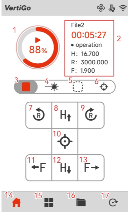
Main Interface
|
1. Start / Pause the job |
2. Display of working hours and coordinates of X, Y and Z axes |
|
3. Stop the job |
4. Pulse button |
|
5. Frame button |
6. Autofocus button |
|
7. The fixture rotates counterclockwise |
8. The laser head moves to the top in the X-axis (H-axis) direction |
|
9. The fixture rotates clockwise |
10. Origin button |
|
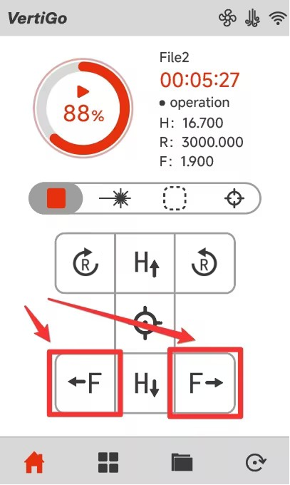
11. The fixture moves to the left in the Z-axis (F-axis) direction |
12. The laser head moves to the bottom in the X-axis (H-axis) direction |
|
13. The fixture moves to the right in the Z-axis (F-axis) direction |
14. Main interface |
|
15. Menu interface |
16. Memory interface |
|
17. Reset button |
|
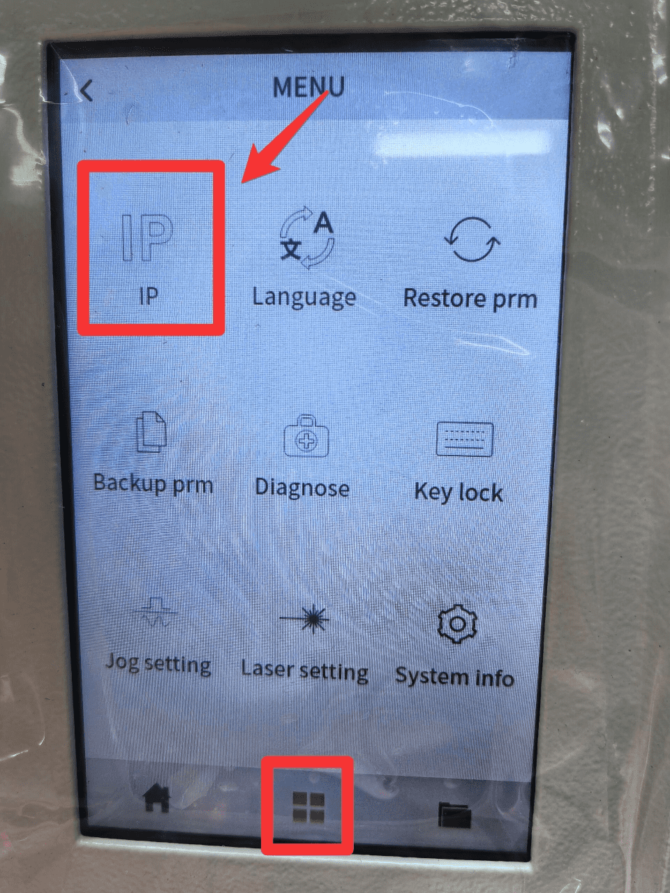
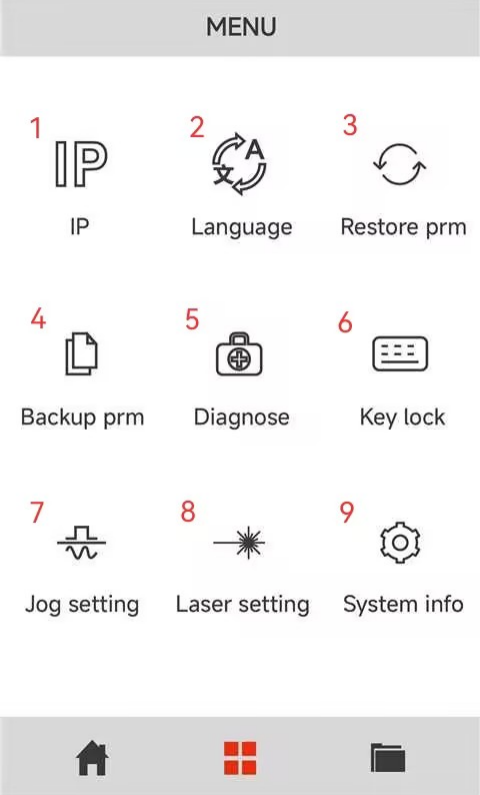
Menu Interface
|
1. Enter the IP address setting interface |
2. Enter the switch language interface |
|
3. Restore factory parameters |
4. Backup current parameters |
|
5. Enter the Diagnostics interface |
6. Keyboard lock to prevent being touched by mis-take |
|
7. Enter the laser head movement settings interface |
8. Enter the pulse settings interface |
|
9. System version information interface |
|
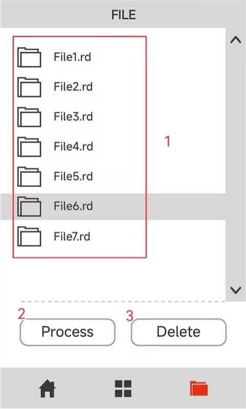
Memory Interface
|
1. The list stores the files that have been transmitted to the various devices |
2. Click on “Process” to process the selected files |
|
3. Click “Delete” to delete the selected files |
|
¶ 4.5 How to Use the Auto-focus and the Manual Focus Function
¶ 4.5.1 Auto-focus Function
The fixture is capable of moving left and right. It will carry the material towards the laser head, making contact with the focusing accessory. Subsequently, it will be adjusted to the appropriate focal length to ensure that an optimal distance is maintained between the material and the laser head. By using the auto focus function, users can focus quickly and accurately before cutting and engraving which saves the time of cutting and engraving and brings the better cutting engraving result.
The diameter range of the processing materials for VertiGo's auto-focus is 89~230mm (3.5”~9.05”).
Please follow the steps below to use the Auto focus function:
Secure the workpiece on the fixture → Click AF button on panel.
After that, the needed focus will be set automatically.
Important: Ensure you press the auto-focus button only once per auto-focus operation.

When using the autofocus function, be careful to avoid the workpiece hitting the laser head, otherwise you will damage the machine and the laser head!
¶ 4.5.2 Manual Focus Function
¶ Case 1: Workpiece Diameter Smaller Than the Auto-Focus Minimum
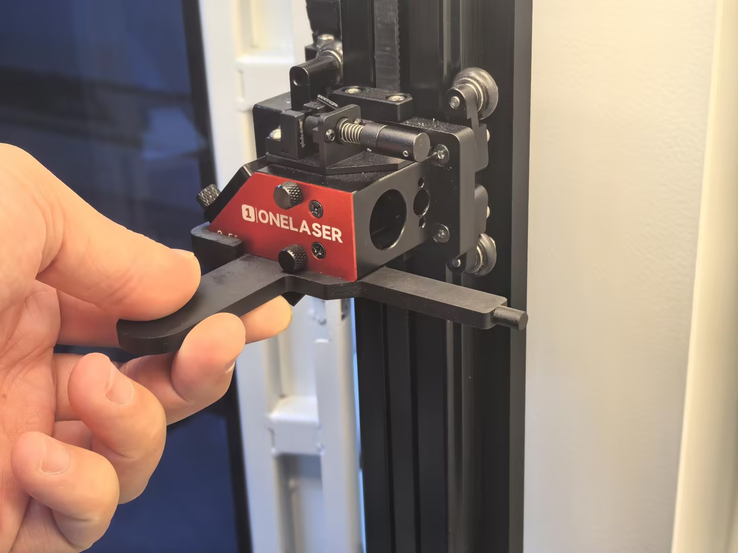
If the diameter of the workpiece to be processed (15–89 mm) is smaller than the minimum diameter supported by the auto-focus system (89 mm), manual focusing is required.
1.Secure the workpiece in the fixture, ensuring it is level and stable.
2.Insert the manual focusing tool along the lower surface of the laser head and align it with the edge protrusion.
3.Adjust the workpiece along the F-axis until it just touches the manual focusing tool.
Note: Use the on-screen controls to move the workpiece left or right along the F-axis.
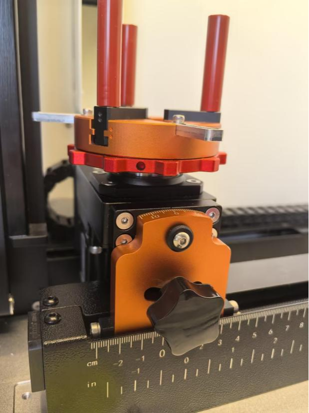
¶ Case 2: Workpiece Diameter Larger Than the Auto-Focus Maximum
If the diameter of the workpiece (230~300mm) to be processed exceeds the maximum diameter (230mm) supported by the auto-focus system, but the diameter at the clamping position remains within the allowable range of the chuck (20~230mm), manual focusing is required.
1.Secure the workpiece on the fixture, ensuring it is level and stable.
2.Note: The adjustment distance corresponds to the radius of the workpiece.
3.Use the on-screen controls to move the workpiece to the right along the F-axis until the distance between the 0° mark on the VertiGo angle marking plate and the 0 cm mark on the bottom F-axis equals the radius of the workpiece.
When using the manual focus function, be careful to avoid the workpiece hitting the laser head, otherwise you will damage the machine and the laser head!
¶ 4.6 The First Time Running the Laser
To be safe, never ever run the laser system unattended.
The following steps describe how to successfully engrave a first pattern. Prepare the device first:
1.Switch on the laser, then wait for the machine is initialized, and the laser head will do the reset and find the home from top left corner.
2. After machine finish resetting, place the workpiece on the working table, move the working table close to the laser head.
①Adjust the height of laser head.
②Run auto focus.
3.Connect the machine with an USB cable or Ethernet cable or WIFI.
¶ 4.6.1 Engraving test
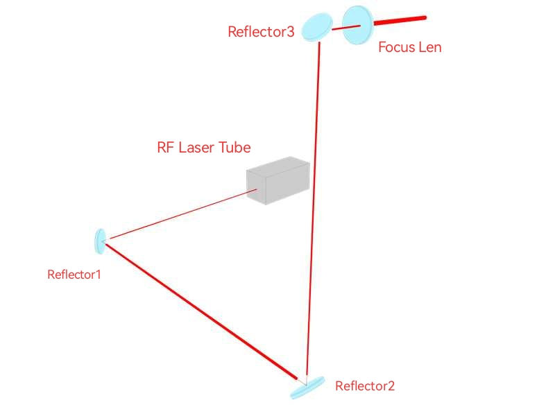
Before leaving the factory, each device undergoes professional calibration to ensure optimal performance. However, during transportation or relocation, pre-aligned components may shift slightly, affecting processing quality. Therefore, users should check the beam path and perform an engraving test before the first formal use.
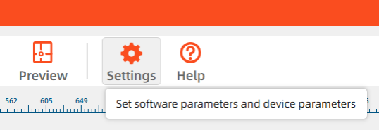
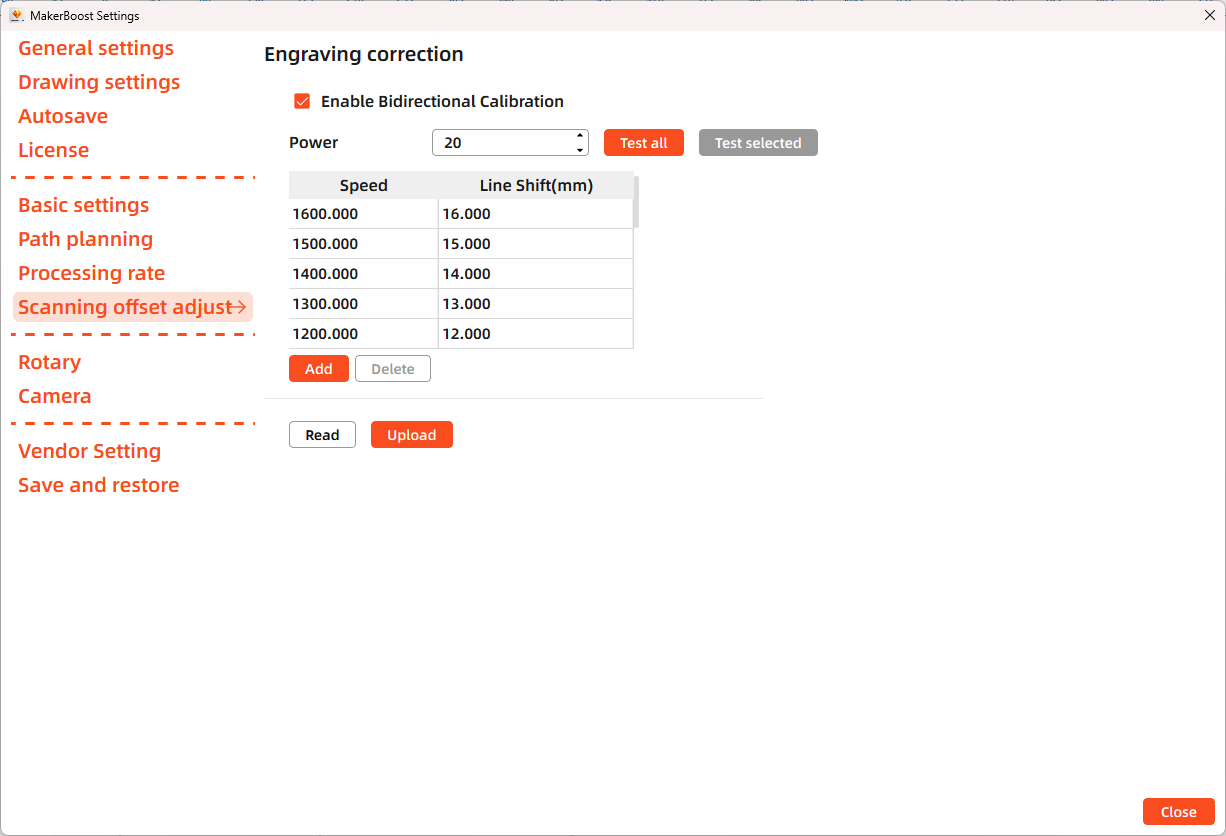
MakerBoost
Open MakerBoost software. Click "Settings" in the top toolbar, then select "Scanning offset adjust" in the dialog window. The software will read existing parameters from the device. Click "Test all" to get results. If misaligned lines appear, measure the distance between both ends of the line at that speed and adjust the "Line Shift" parameter.
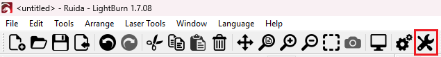
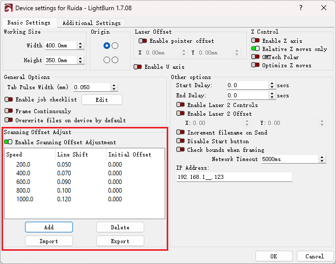
Lightburn
Open Lightburn software. Go to Devices Settings - Enable Scanning Offset Adjustment. Notice: Lightburn cannot read existing device parameters; users must manually enter values.
The particular values are showing with a picture in folder of laser software on the USB flash drive and on the Anodized aluminum piece that came with your machine.
¶ 4.6.2 Formal Engraving
After completing tests, you may formally operate the VertiGO. Create any text, graphics, or images using MakerBoost or Lightburn. Then set up the parameter and download the file to your machine.
- Control arrow button to move the laser head;
- Click "Origin" button to select the start point;
- Click "Frame" button on the display, please make sure that the material is in the right location and there is enough space for working.
- Finally press the "Start" button in the display, to start the engraving process.
When the engraving is complete, the laser machine will give out the notification sound and the laser head will go back to the original point, and the warning light will return to the green light, then you can repeat engraving. Please make sure the unit is in mm instead of inch.
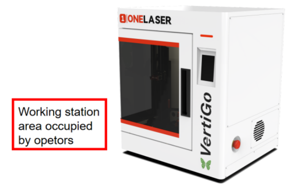
¶ 4.7 Workstation Area Indication
¶ 4.8 For Laser Engraving
The engraving depth can easily be varied through the laser power or the speed. To increase the engraving depth, reduce the speed or increase the power setting. This way you increase the amount of energy per area unit. Engraving too deep, however, reduces the quality of the details. With coated materials the required power depends of the kind and thickness of the coating. With power set too high the individual lines become too thick and a sharp picture cannot be achieved. The resolution of the graphics should usually be at 500 dpi. The dpi setting (number of laser dots per inch) depends on the material. The lower this setting is, the lower the resolution of the engraved picture will be. This, however, reduces flaming and increases the energy of a pulse, which can improve the overall result (e.g. when engraving some sorts of plastic materials).
1.Plastics
Plastics for engraving are available in many different colors and thicknesses and with many different coatings and surfaces. The majority of available plastics can be well engraved and cut with the laser. Plastics with a micro-porous surface seem to give the best result, because less surface material needs to be removed. As most plastic materials have a low melting point, a low pip setting should be selected to reduce the danger of melting.
2.Engrave the stainless steel
The various mixtures and densities of stainless steel cause a slightly varying engraving depth. Since engraving a stainless steel material requires a relatively high laser power, the laser power is principally set to suitable power and find out the correct speed setting.
¶ Chapter 5. Maintenance
¶ 5.1 Clean the Laser Machine
Caution – use of controls or adjustments or performance of procedures other than those specified here in may result in hazardous laser radiation exposure.
Before starting cleaning and maintenance work always switch off the device and unplug the mains plug. Always keep the system clean, as flammable parts in the working area or exhaust area rise the fire hazard.
You should check at least once a day, whether dust has accumulated in the engraving system. In case of soiling the machine must be cleaned. The cleaning interval strongly depends on the material that is being processed and the operating time of the device. Please bear in mind that only a clean machine guarantees optimal performance and reduces the service costs.
General Cleaning Notes:
1. Make sure that the device is switched off and unplugged. Open the protective cover.
2. Move the working table into a position in which it is easiest for you to clean the surface with a window cleaning agent and paper towels.
3. Thoroughly remove all loose dirt particles and deposits in the interior of the machine.
4. Clean the cover of the laser tube.
5. You can clean the viewing window with a cotton cloth. Do not use paper towels as they could scratch the window.
6. The laser nozzle should be cleaned regularly to prevent oil and grease buildup from obstructing the laser beam. It is recommended to clean the laser aperture every three days.
¶ 5.2 Clean the Optical Parts
These mirrors have durable multi-coating and won’ t be damaged by correct and careful cleaning. You should inspect the focus lens and the reflectors and the beam combiner according the maintenance plan. If you discover a veil of haze or dirt, you must clean them.
It is suggested to clean the reflectors/lens before work every day in order to run the machine at max efficiency.
Please turn off the power of laser machine before cleaning the optical parts.
1.The lens and the reflectors must be cleaned carefully with a clean cotton swab or a dust-free cloth to avoid scratching the surface of the lens.
2.Do not touch the lens with your hands after wiping.
3.Never use a cleaning swab or a dust-free cloth twice.
¶ 5.2.1 Clean the Focus Lens
1. Take the lens out.
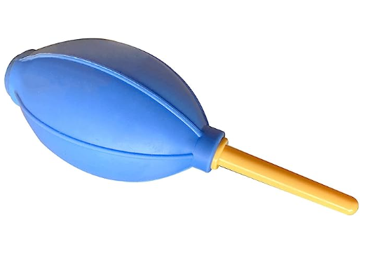
2. Remove the coarse dust as good as possible by blowing air onto the lens surface.
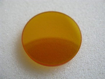
3. Clean the lens with the cleaner and swabs.
4. Dry this side of the lens with dry cleaning swabs and repeat the cleaning process on the other side of the lens. Never use a cleaning swabs twice. Dust accumulated in the cleaning swabs could scratch the lens surface.
5. Examine the lens. If it is still soiled, repeat the cleaning process until the lens is clean. Finally, install the lens back.
¶ 5.2.2 Clean the Reflectors
1. Remove the coarse dust as good as possible by blowing air onto the mirror surface.
2. Clean the lens with the cleaner and swabs.
3. Dry this side of the mirror with dry cleaning swabs and repeat the cleaning process on the other side of the mirror. Never use a cleaning swabs twice. Dust accumulated in the cleaning swabs could scratch the mirror surface.
4. Examine the mirror. If it is still soiled, repeat the cleaning process until the lens is clean.
¶ 5.2.3 Clean Laser Combiner
1. The laser combiner is installed in front of the first mirror.
2. Remove the coarse dust as good as possible by blowing air onto the combiner surface.
3. Clean the lens with the cleaner and swabs.
4. Dry this side of the laser combiner with dry cleaning swabs and repeat the cleaning process on the other side of the lens. Never use a cleaning swab twice. Dust accumulated in the cleaning swabs could scratch the combiner surface.
5. Examine the laser combiner. If it is still soiled, repeat the cleaning process until it is clean.
¶ 5.3 Check the Beam Path
After being used for a long time, the beam path might be deflective. This will reduce the efficient of the laser beam or even cause no laser beam. At this moment, you will need to re-adjust the beam path again.
¶ 5.4 Clean the Inside of the Machine
Remove small pieces that fall into the work table, gears, rails, and belts with a small brush or vacuum cleaner.
Work Area
Gears
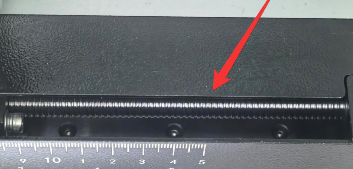
Belt
Notice: If the belt is severely worn, it needs to be replaced.
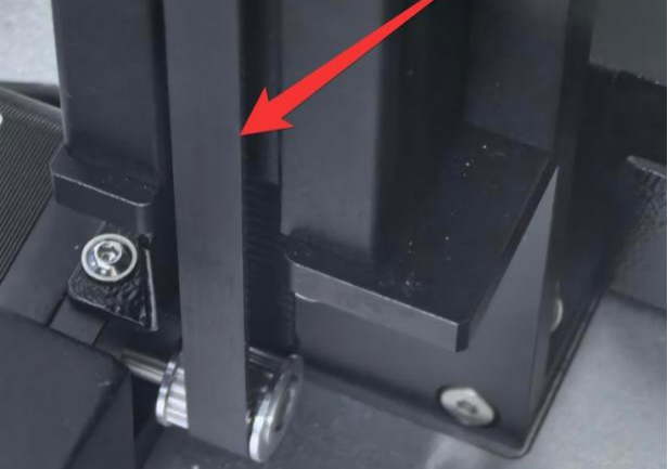
Rails
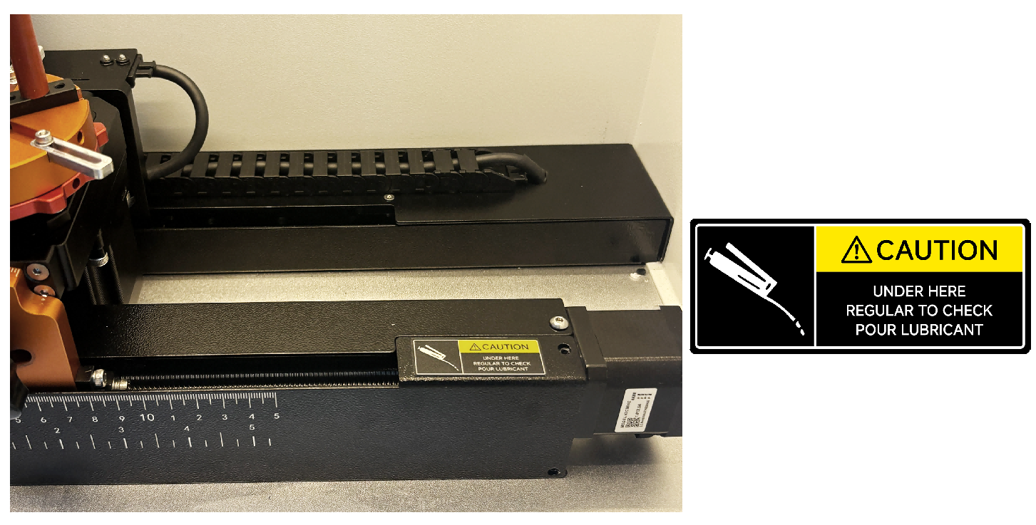
Notice: It is advisable to apply some lubricating oil to the lead screw from time to time to prevent wear.
Exhaust Port
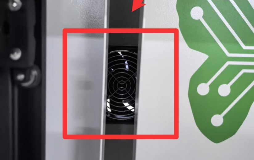
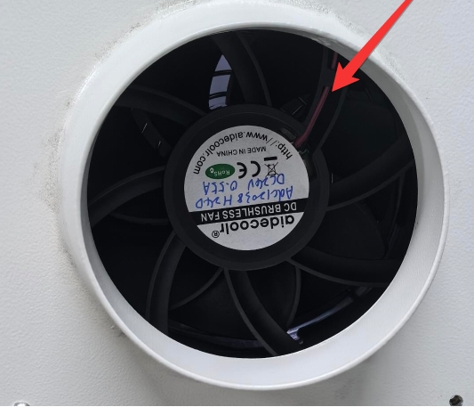
RF Tube Cooling Fan
¶ 5.5 Maintenance Plan
Please strictly follow the maintenance instructions in this manual to maintain the machine. Failure to adhere to these instructions or using incorrect maintenance methods may result in machine damage, affecting its performance and potentially voiding the warranty.
| DAILY | WEEKLY | 3 MONTHS | 6 MONTHS | 12 MONTHS |
| Lens | Mirror 2 and 3 | Mirror 1 | Belts | Overall Machine |
| Auto Sensor | Work Table | Exhaust Fan | Bearing and Rails | |
|
Vent Slots (back side of the machine) |
Interior Work Space |